B&W 801 Series 80 Restoration (1983)
All the photos
I scored these off KSL Classifieds (local goods exchange here in UT) for a steal as I managed to message the seller first. There was nothing really wrong with the speakers, they sounded great! However, I knew they were ~40 years old (confirmed after I got inside them, these were built in 1983) and the caps at least probably needed replacing. I found crossoverchef.com selling rebuilt crossovers on ebay (example listing) and figured that was better than attempting things myself. Honesty, the PCB intimidated me and I wanted to break out the High Frequency (HF) and Low Frequency (LF) so I could bi-amp the speakers. This page documents my journey in restoring these beautiful speakers and making them better!
2) Final listening test before tearing into them
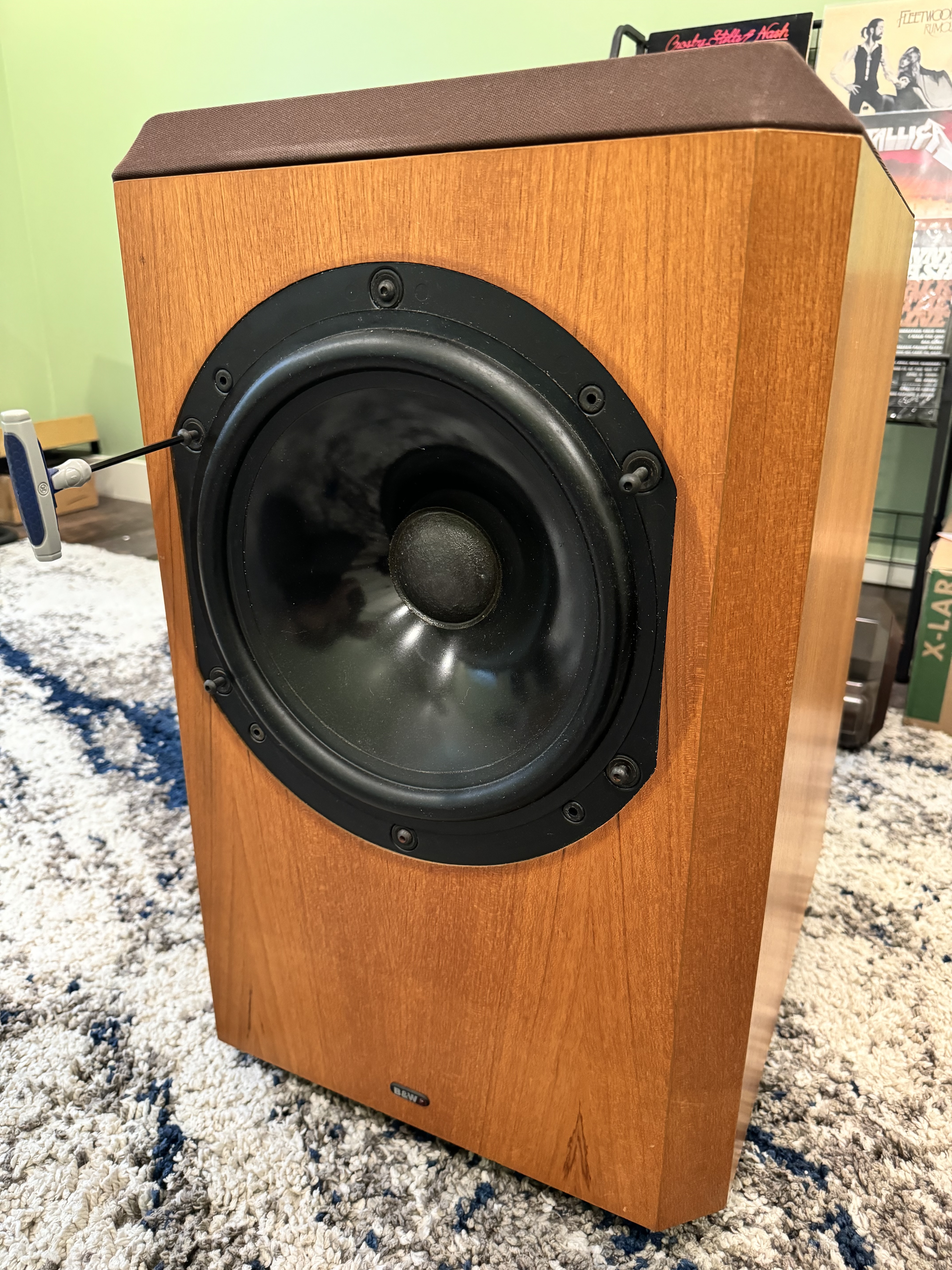
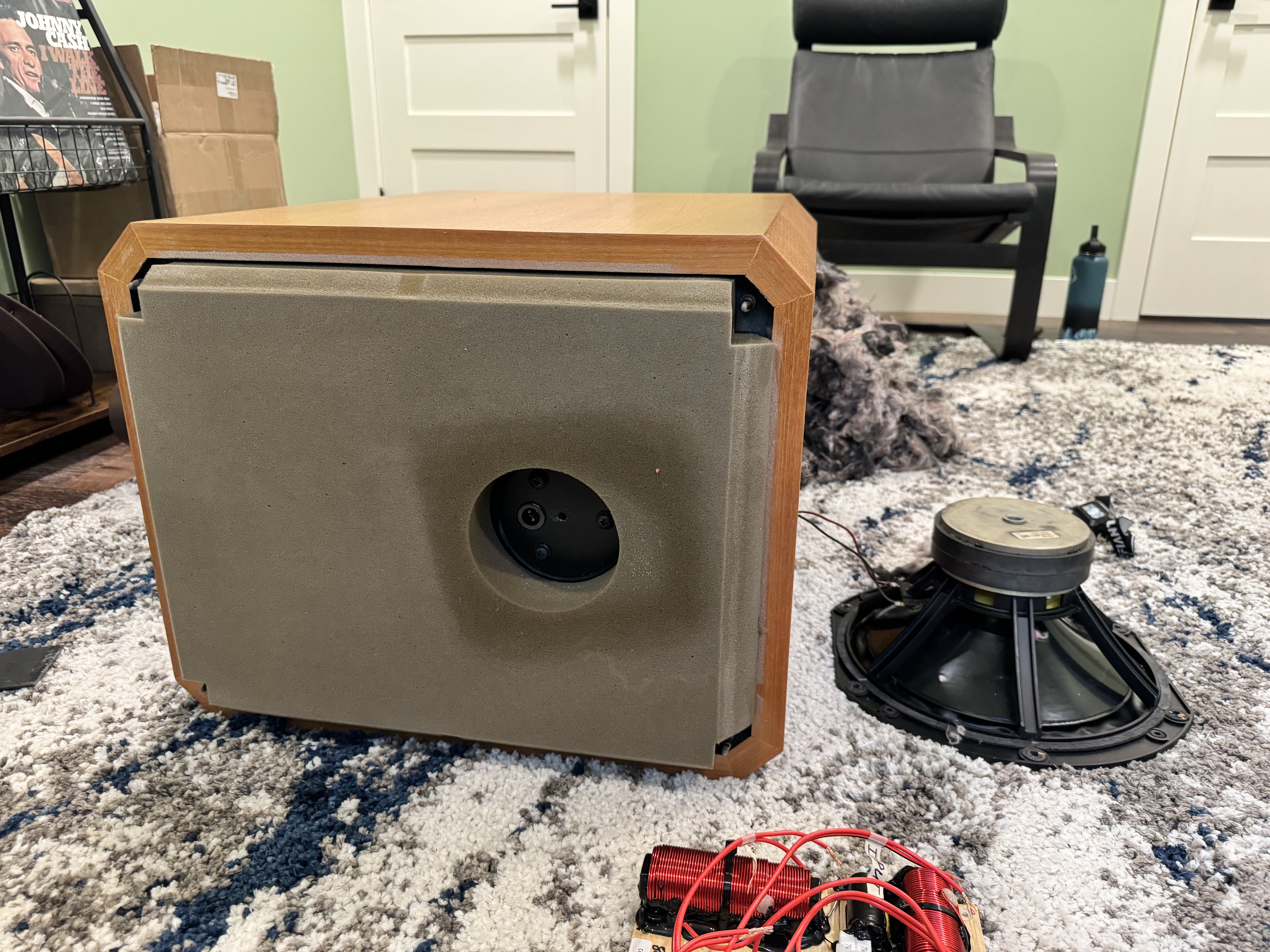
3) Here we go! Remove the woofer
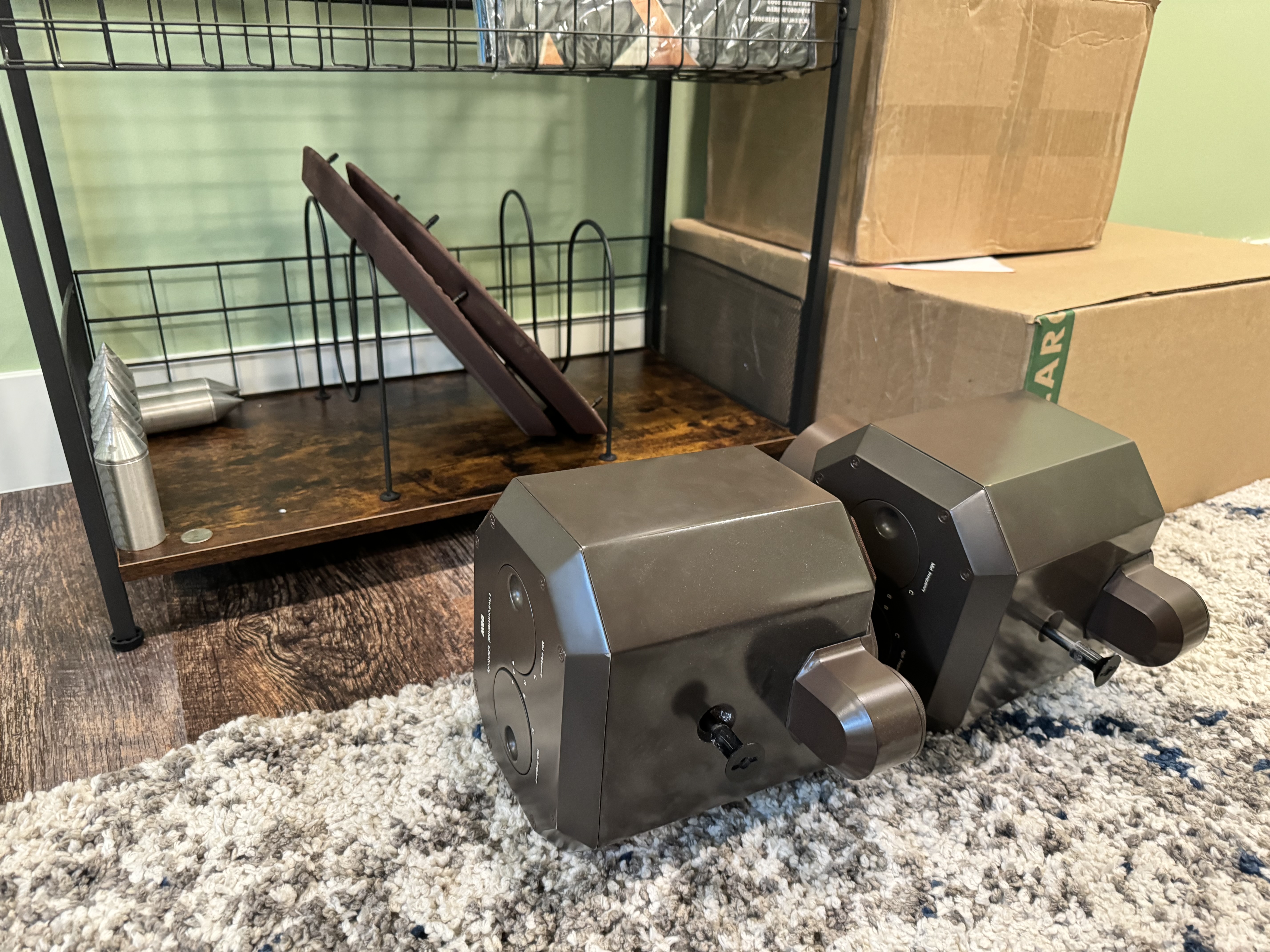
4) Mid-range and tweeter heads removed, spikes removed, set aside
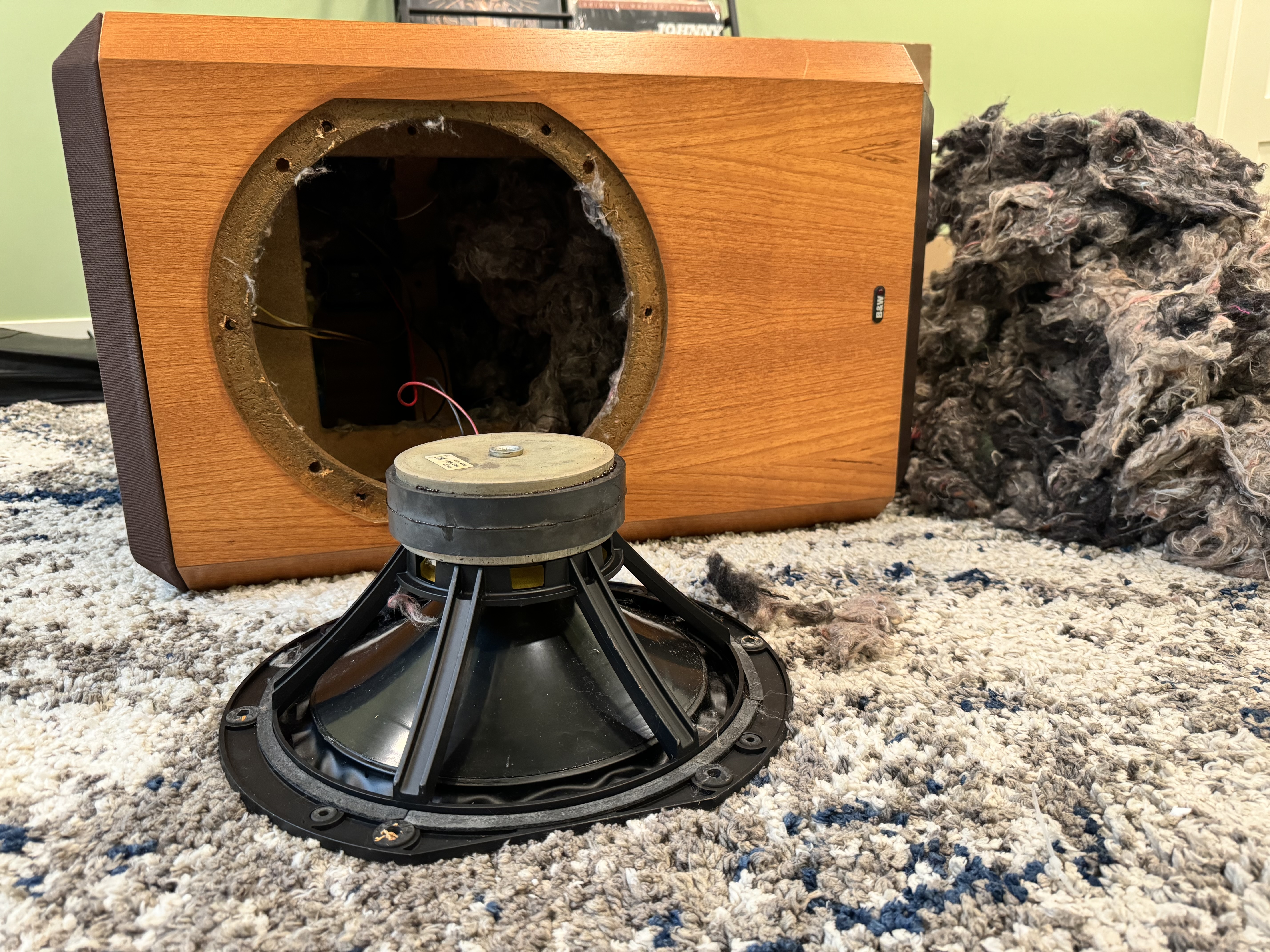
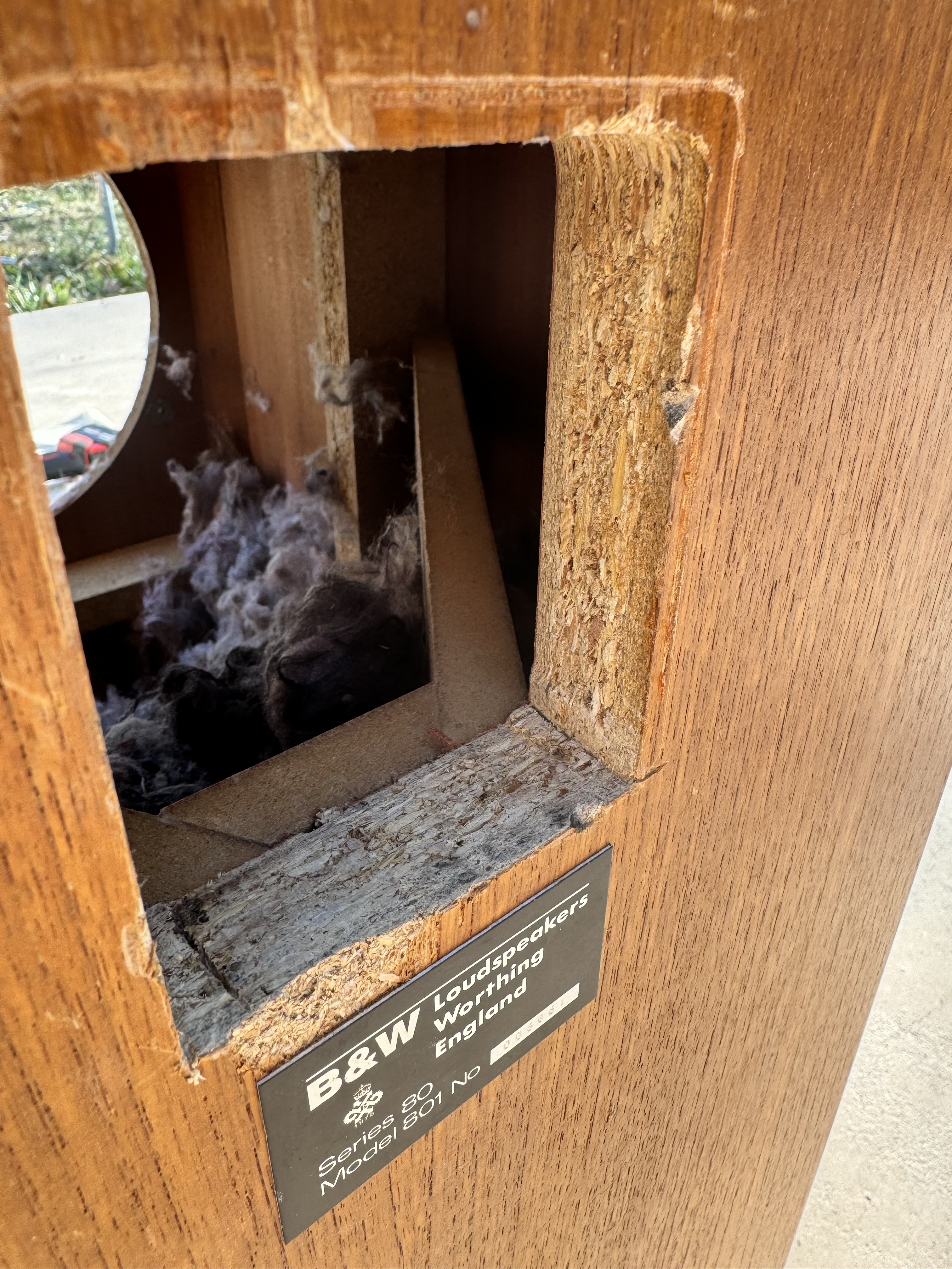
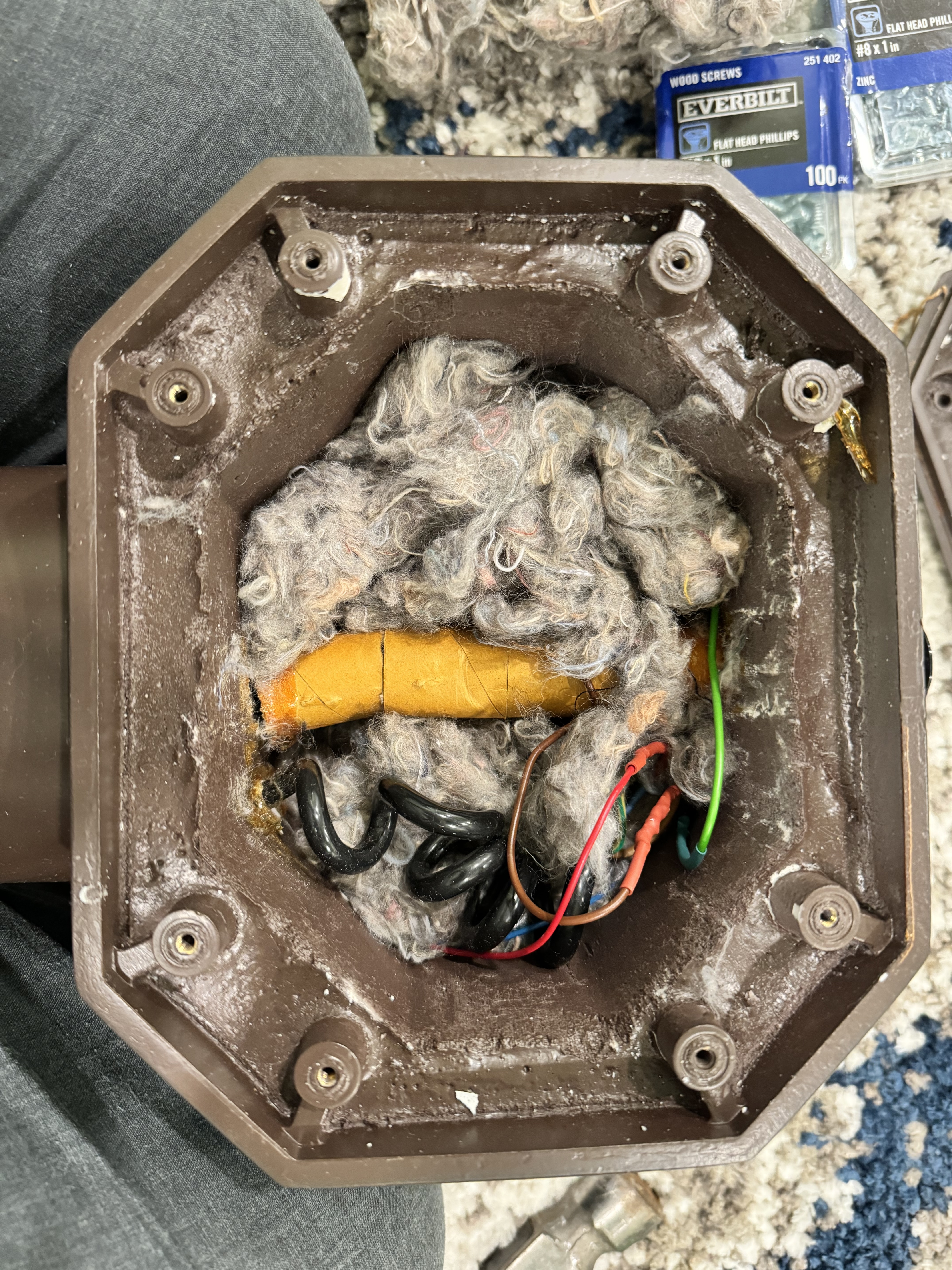
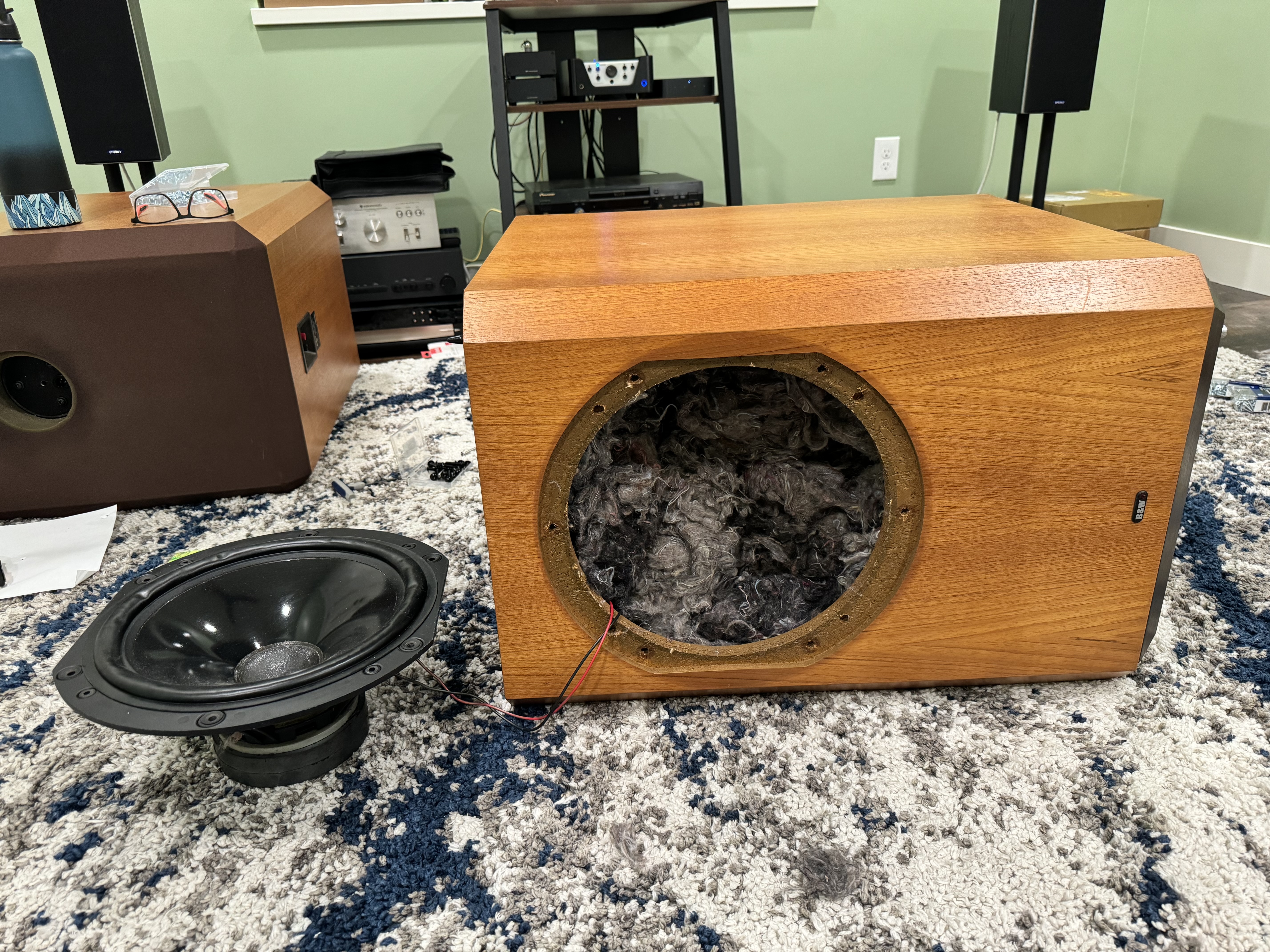
5) Woofer removed, some of the internal wool(?) set aside. I end up removing all the wool from the top half but leave the stuff in the bottom (there's a ton!)
6) All the wool removed from the top half
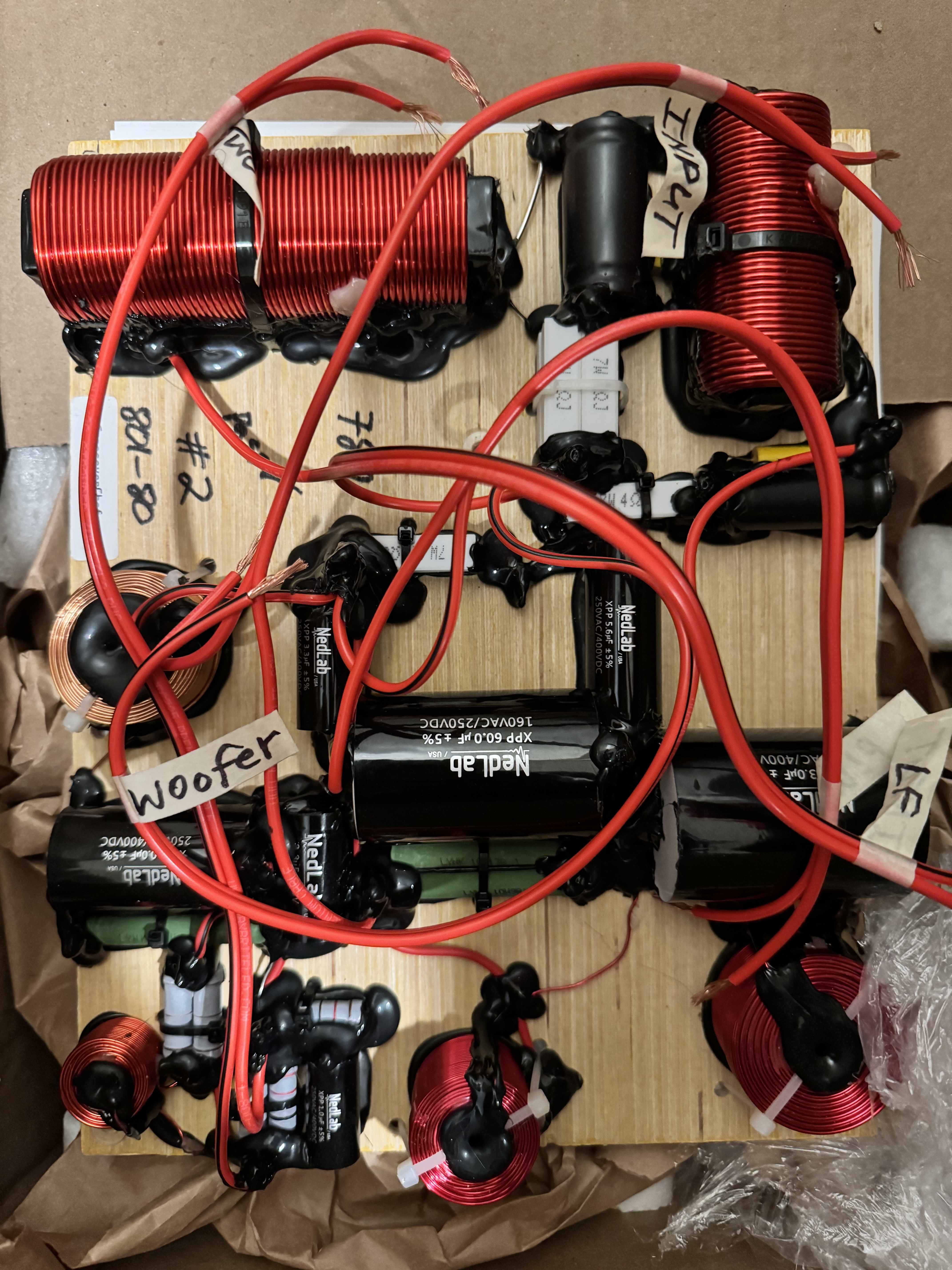
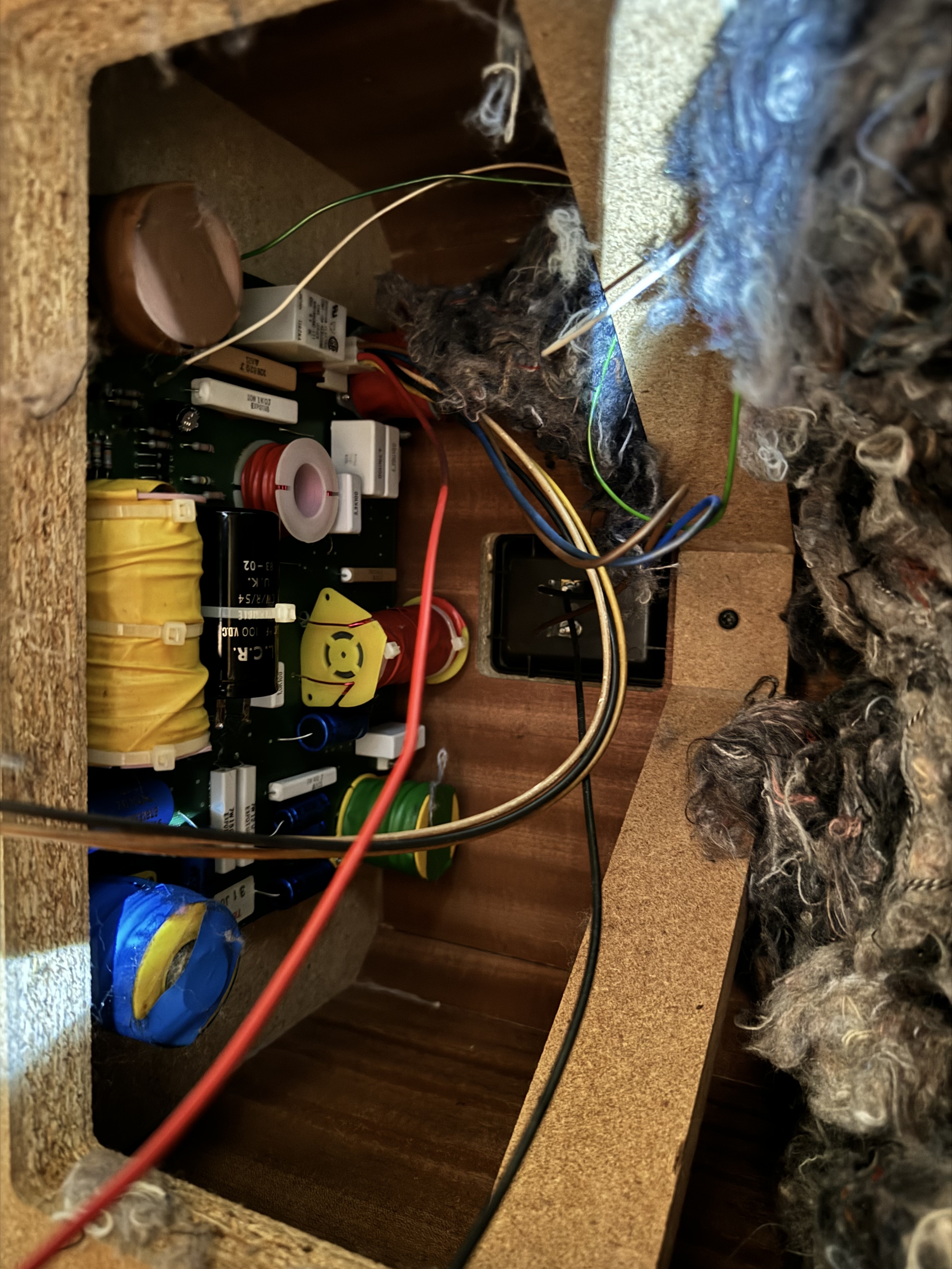
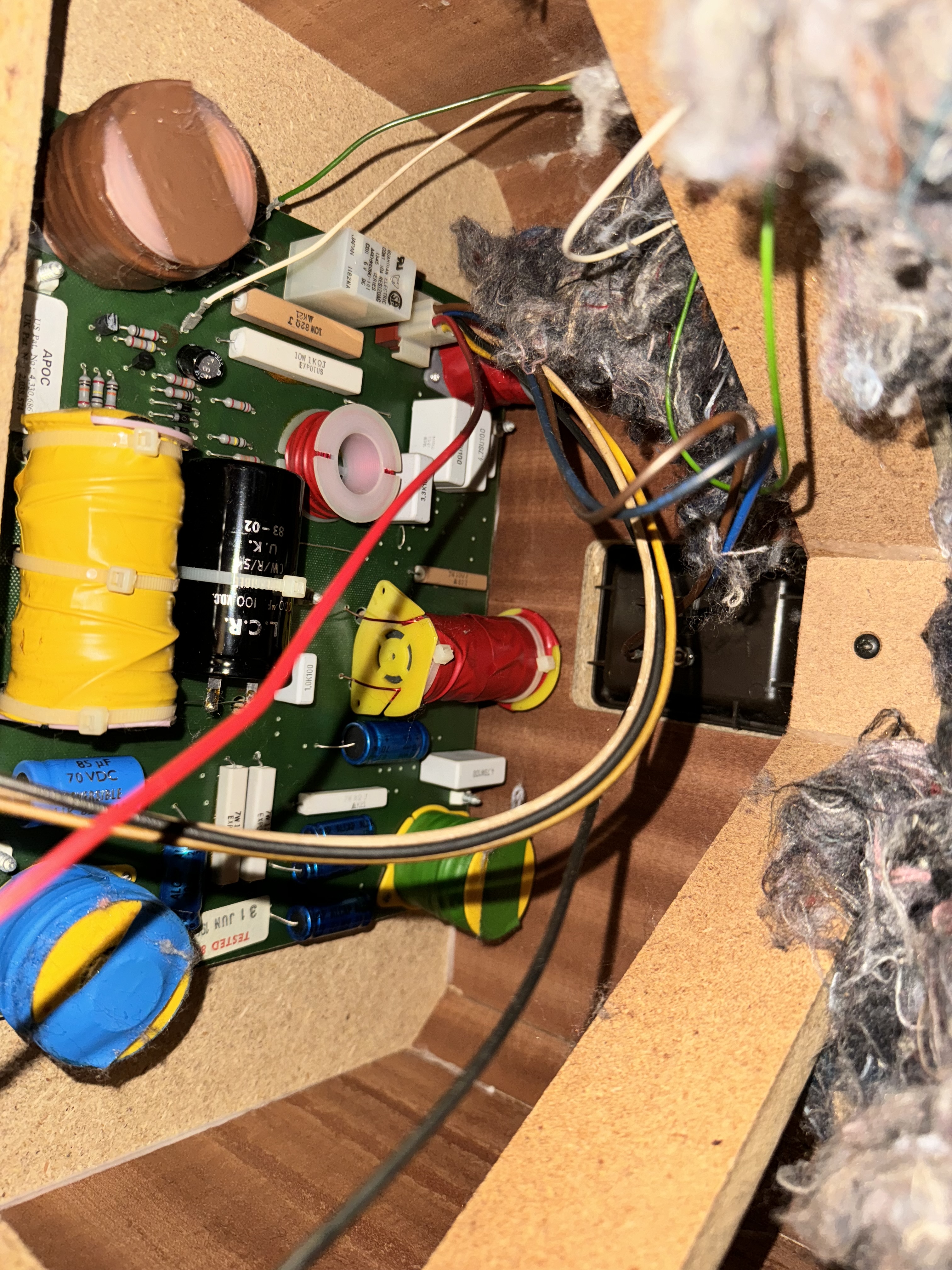
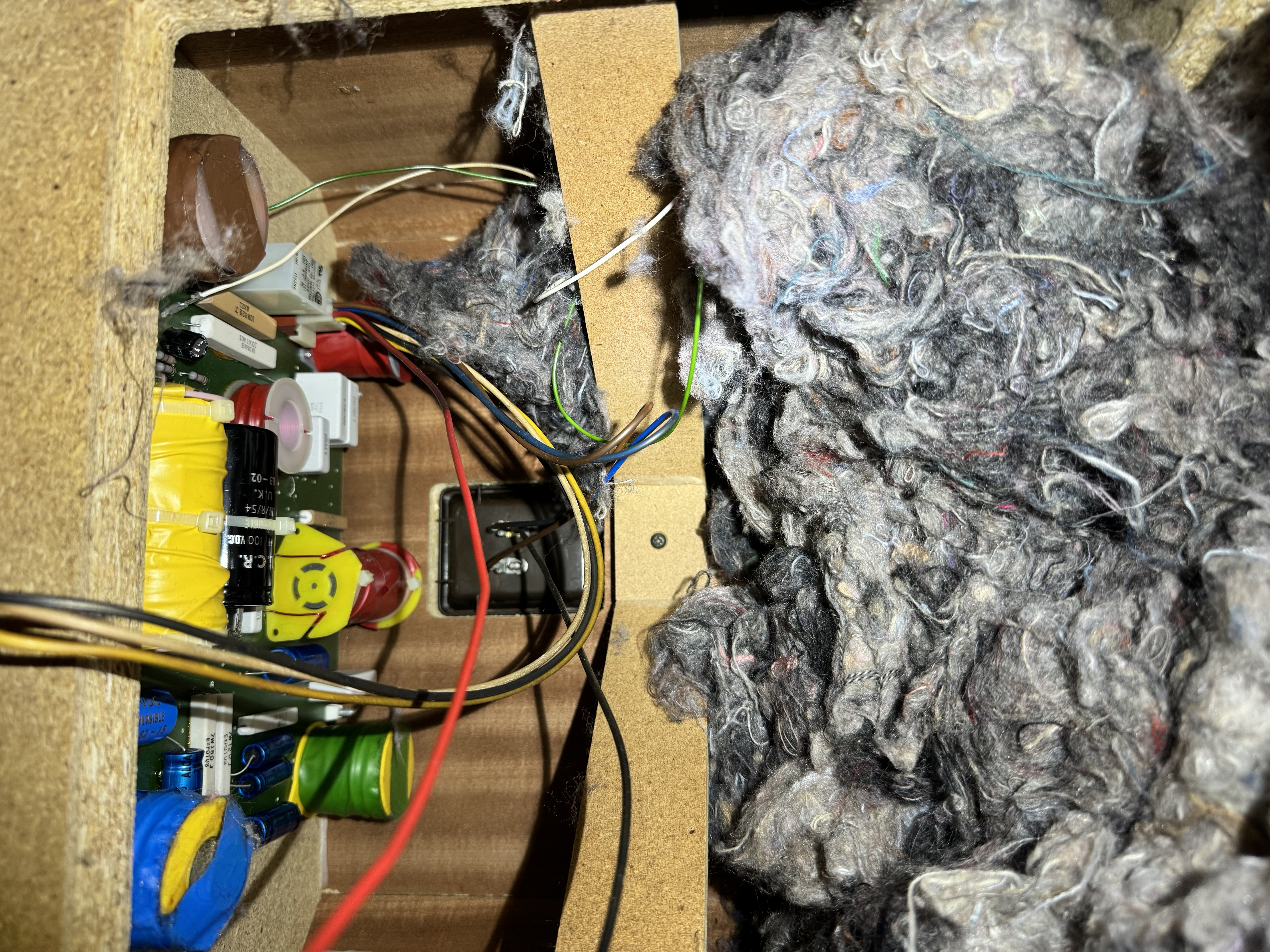
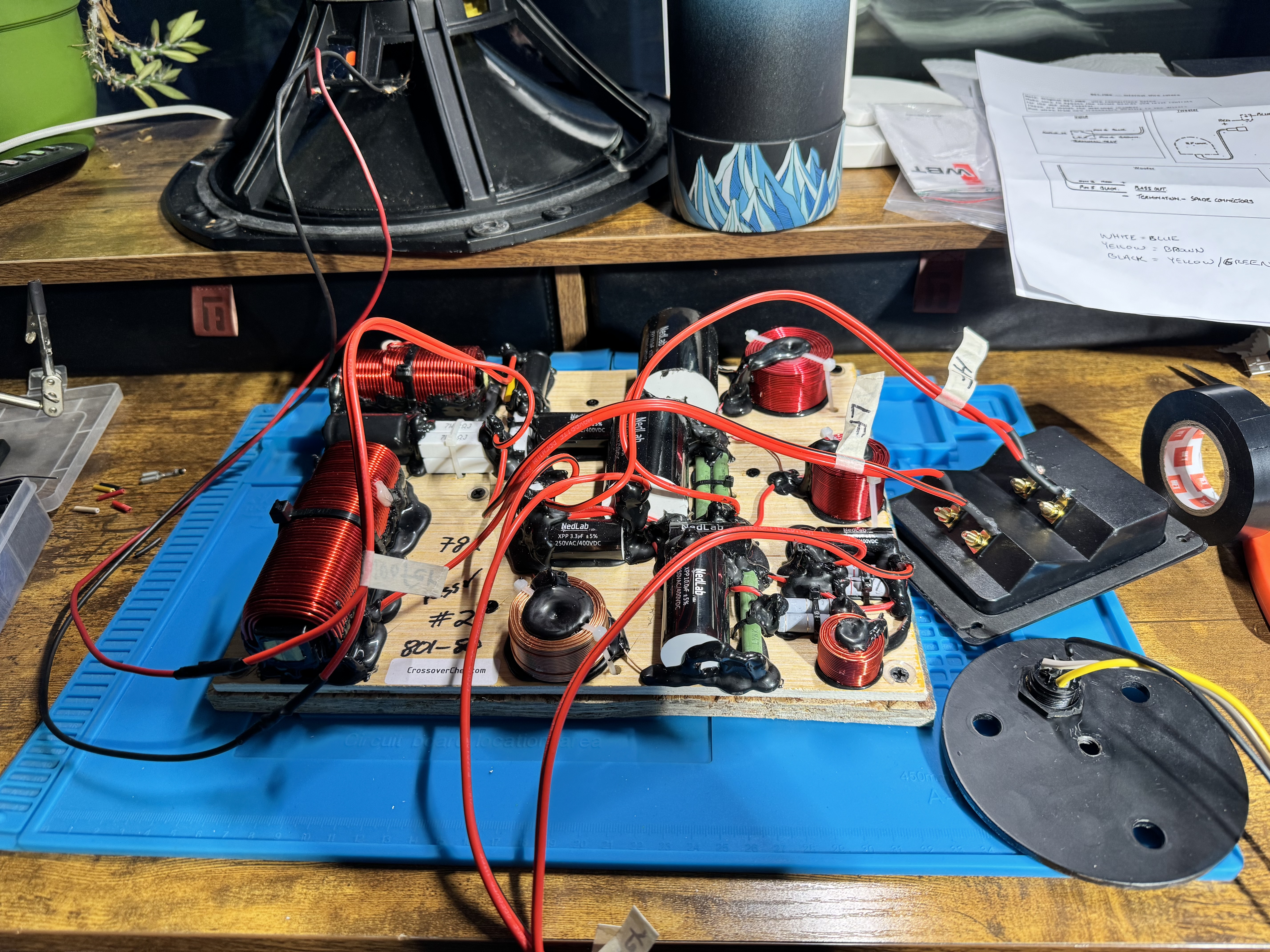
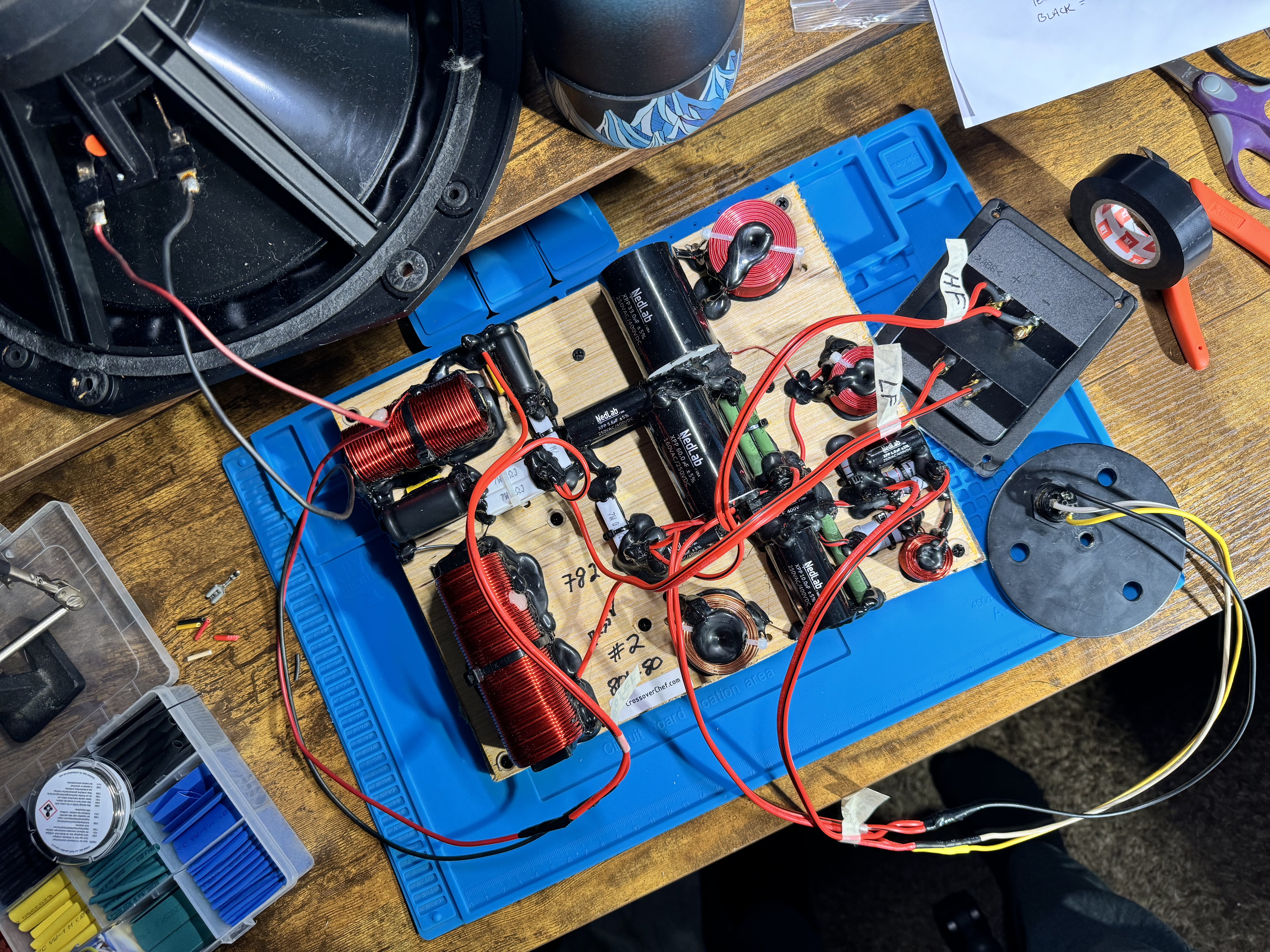
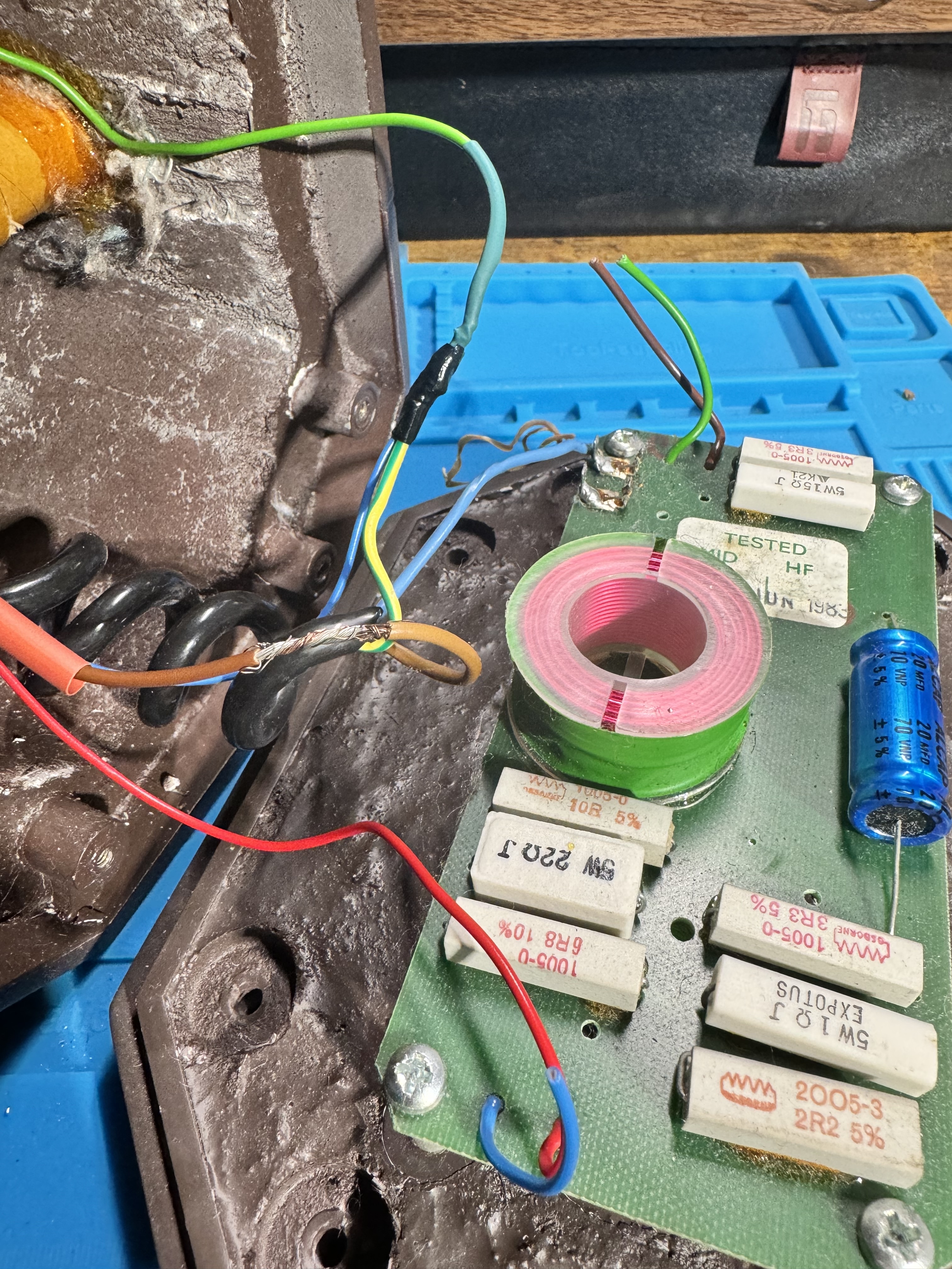
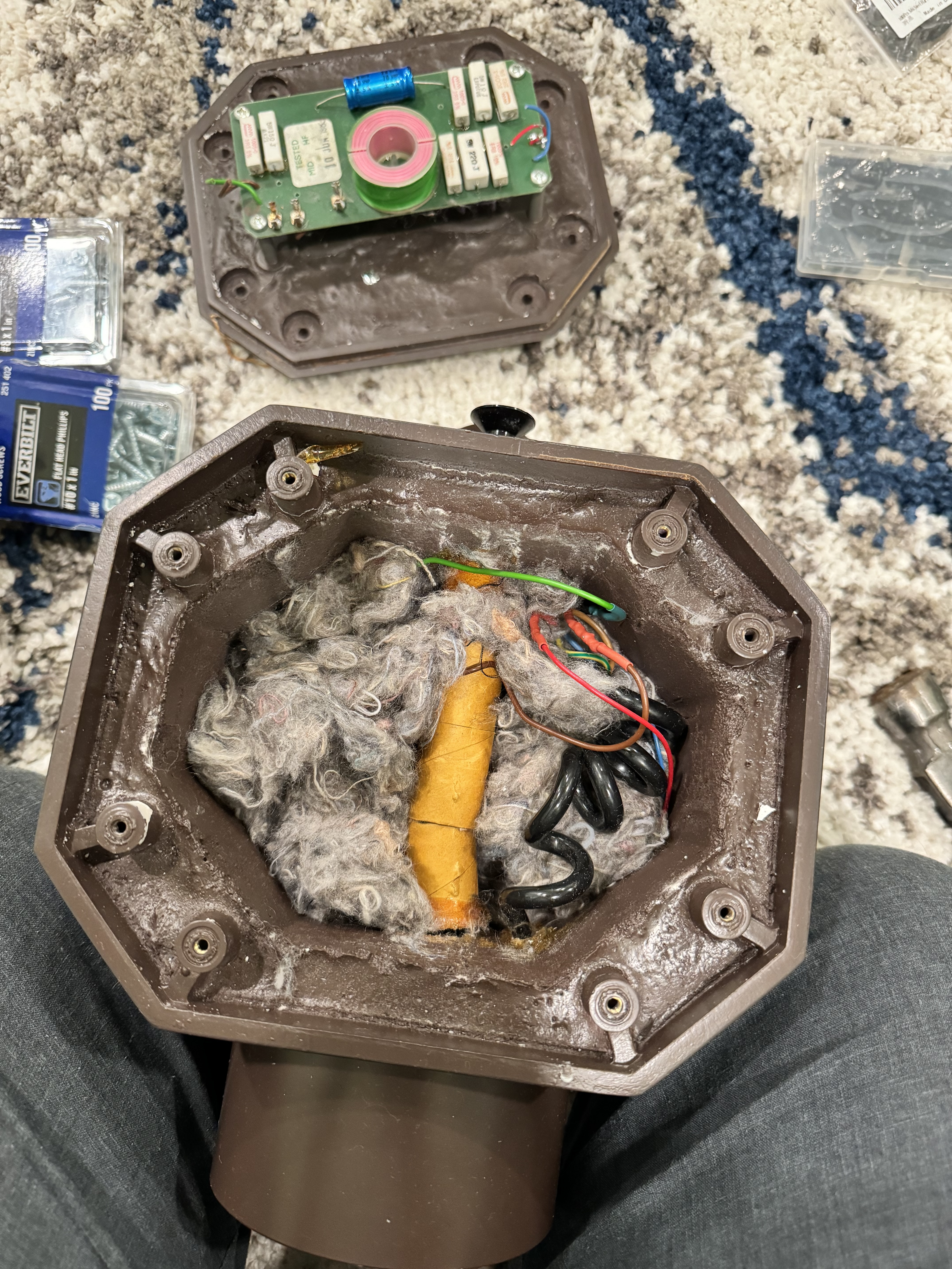
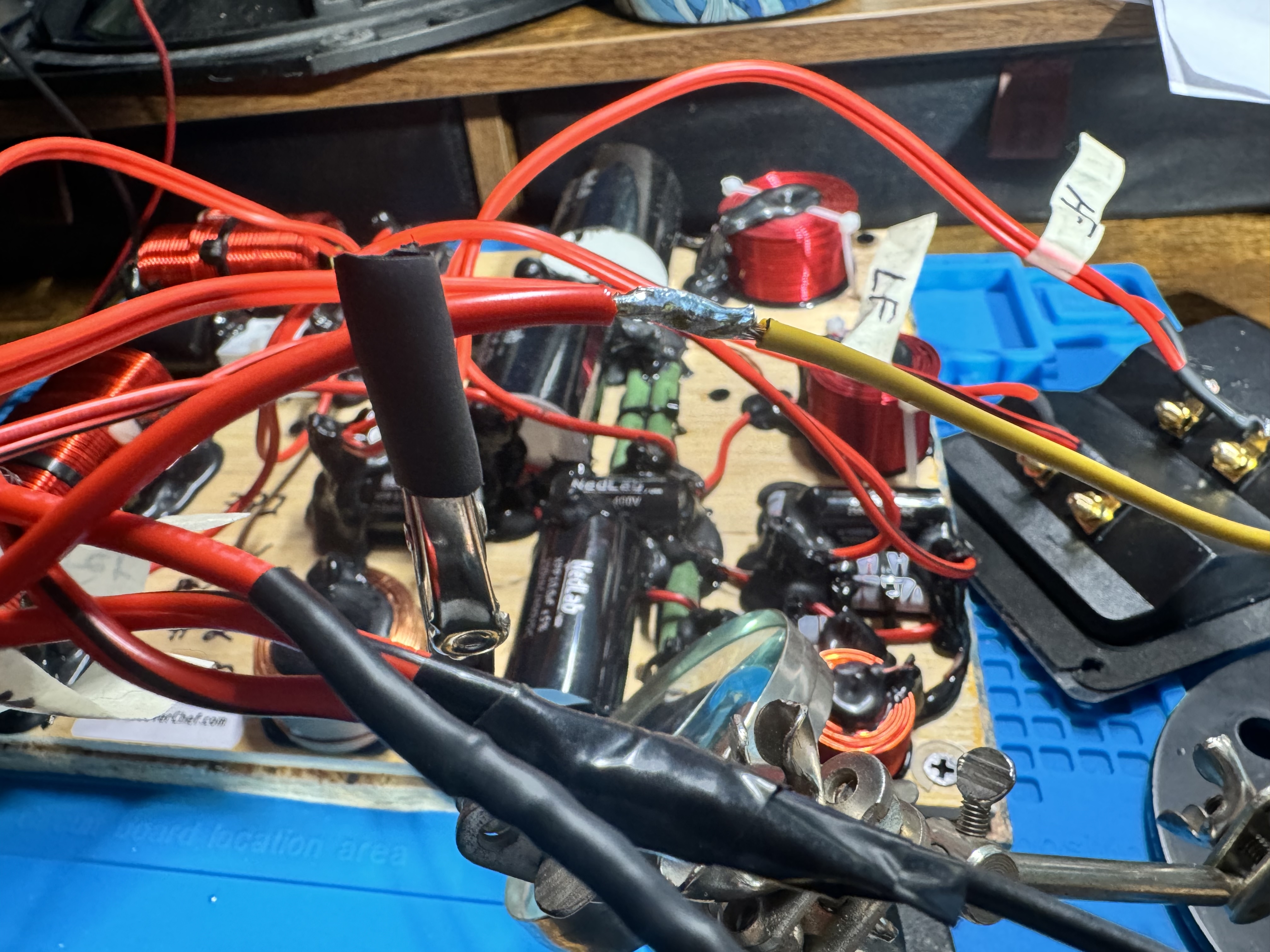
7) Original woofer crossover as I found it
8) Better lighting of original woofer crossover
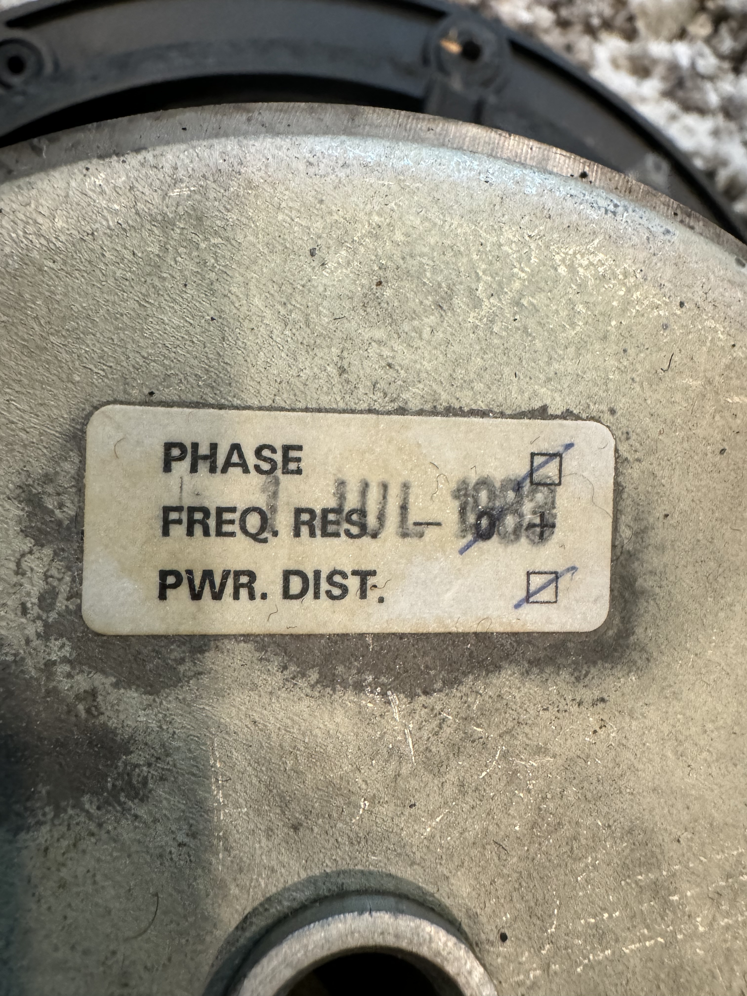
9) Woofer tested 1 July 1983
10) I never knew the top "grille" cover came off, but I always suspected. Works just like any other speaker cover, pops off, big foam pad underneath
11) Removed foam pad, there's the screws for the woofer crossover!
12) Another shot of the crossover to show where original wires go
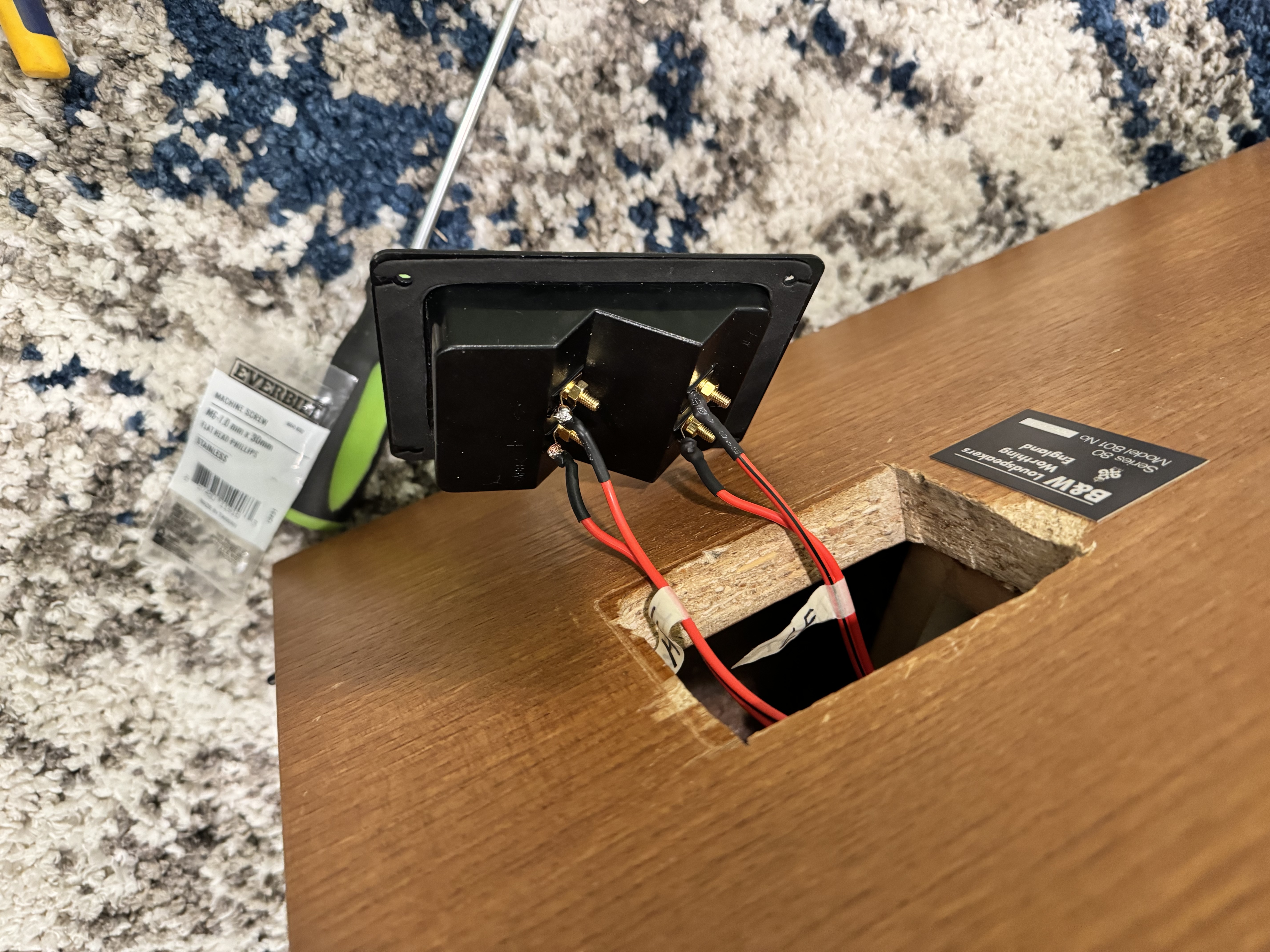
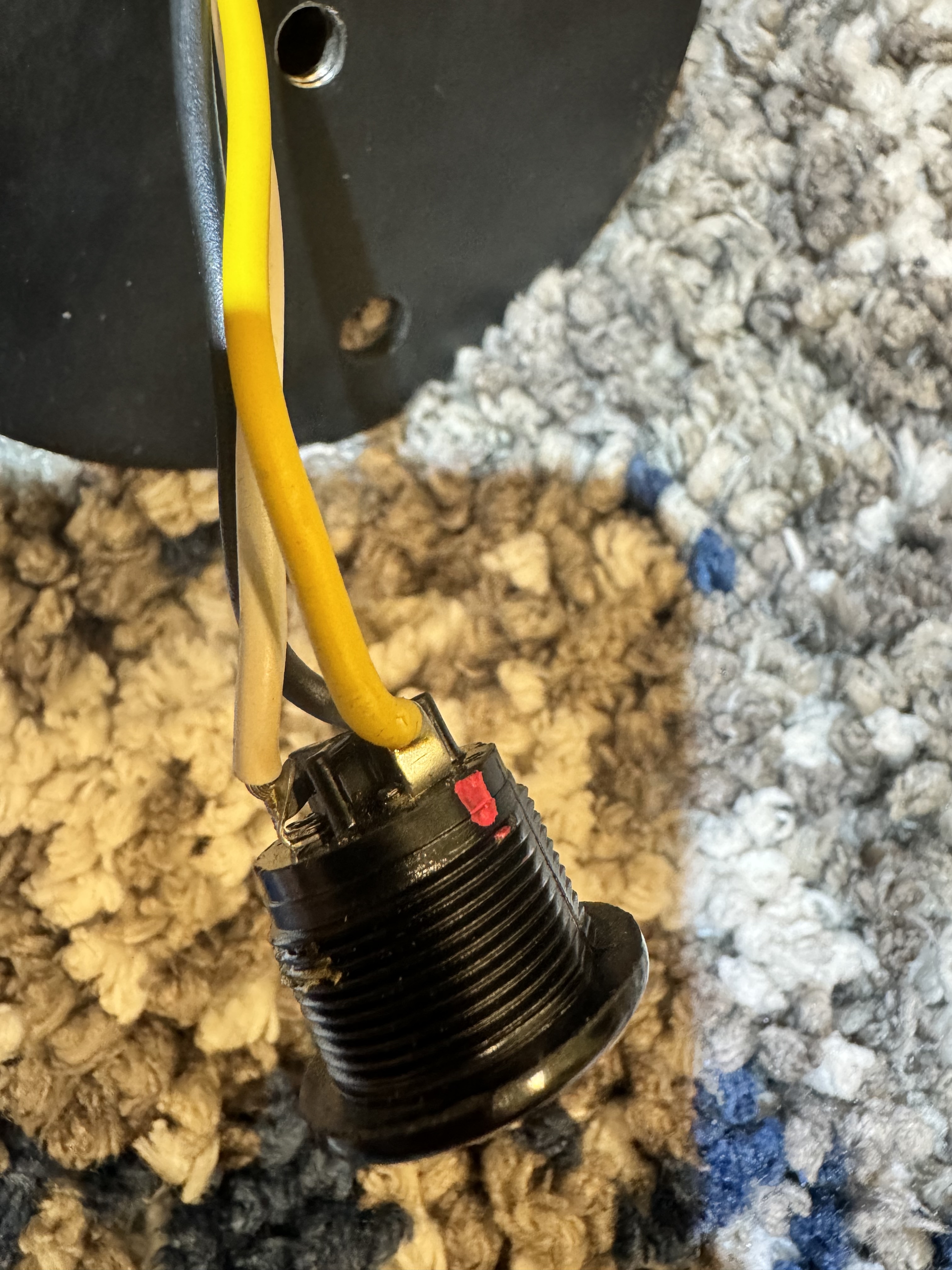
13) Unplugging the binding posts (input) and the woofer crossover network (very similar to an internal PC connector plug, but obviously proprietary)
14) Removing the screws holding the woofer crossover
15) Original woofer crossover removed. Note the June 31, 1983 date at the bottom. The white plastic things are what the screws grabbed onto
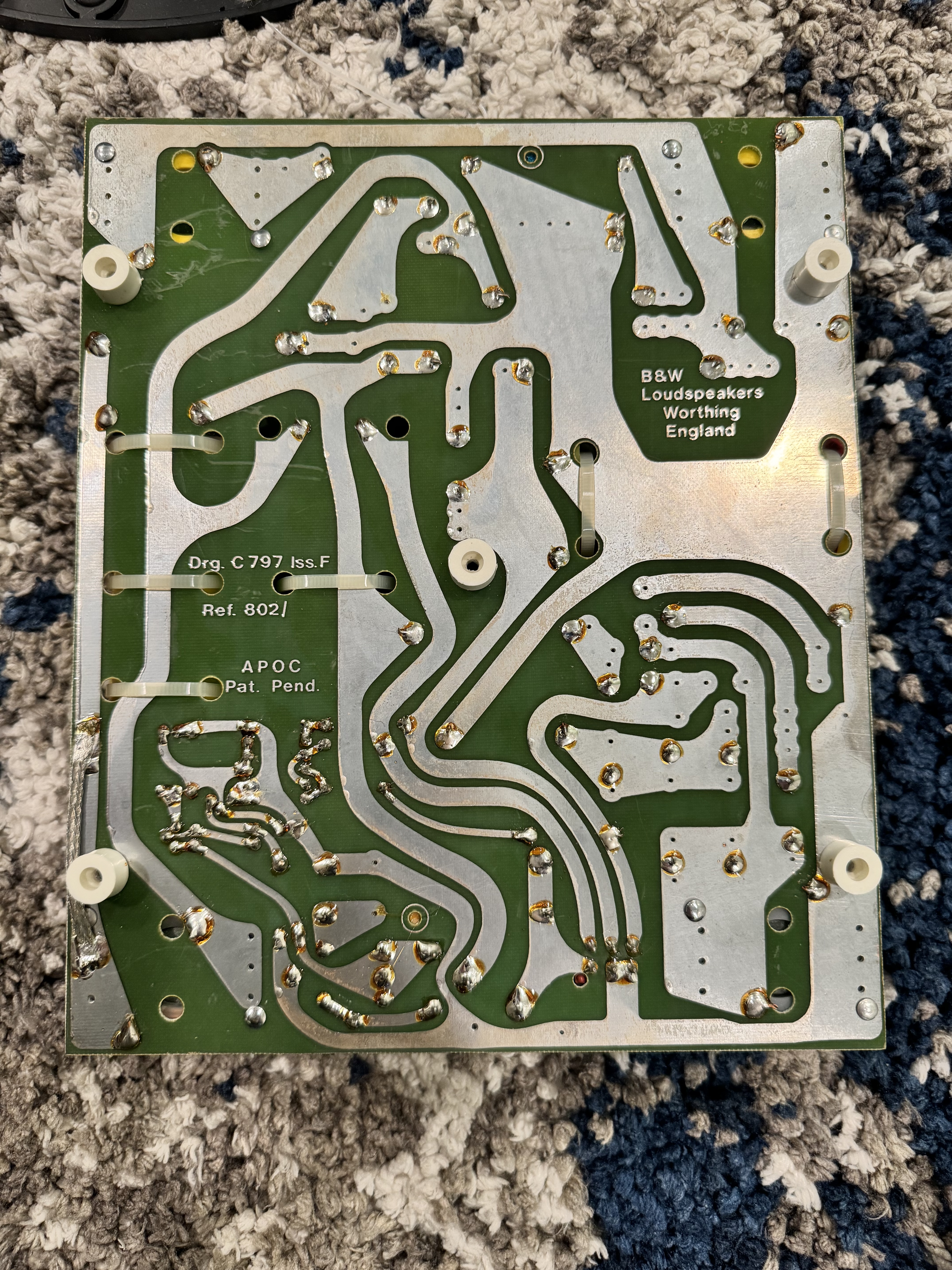
16) Back of original woofer crossover
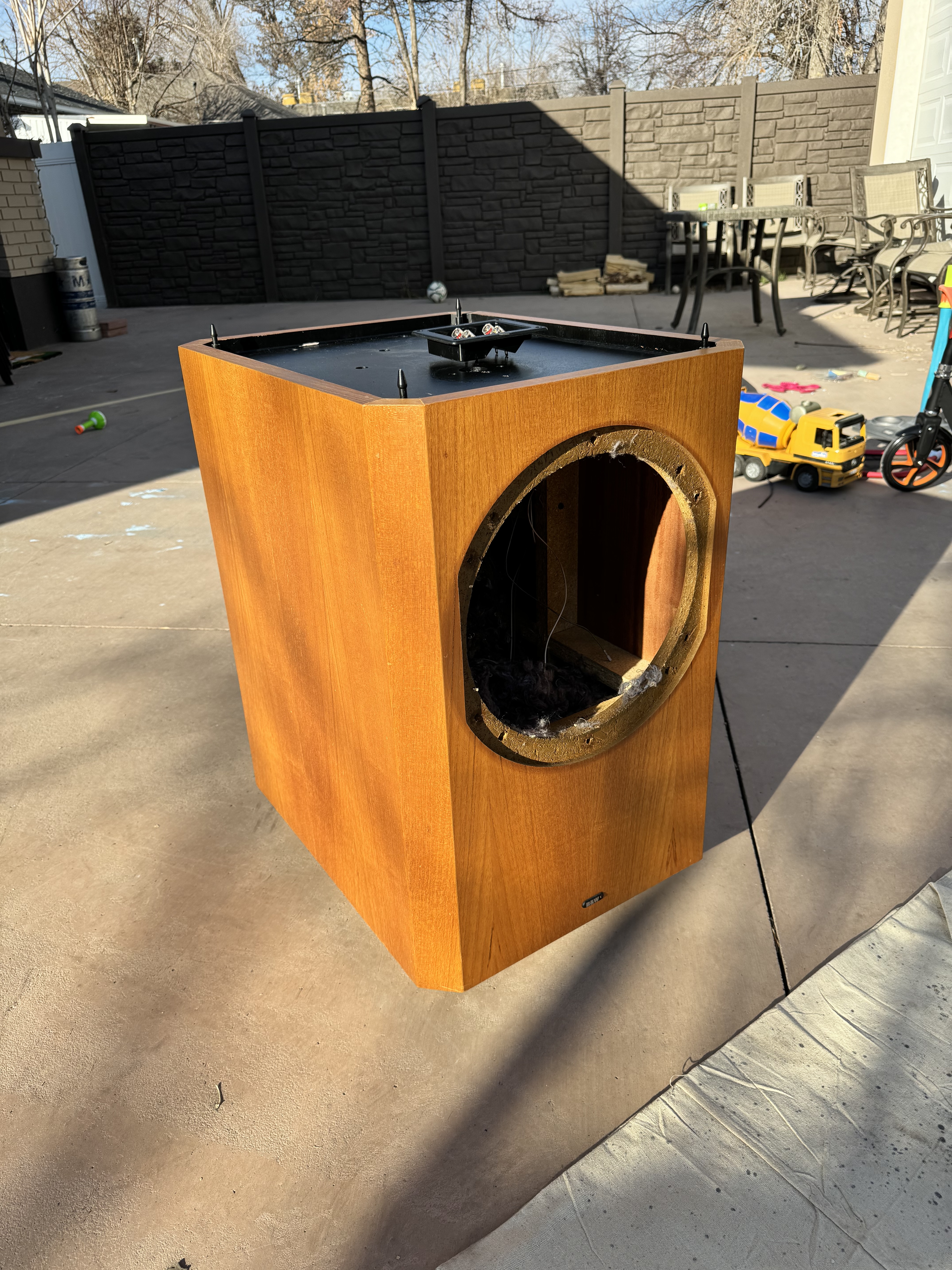
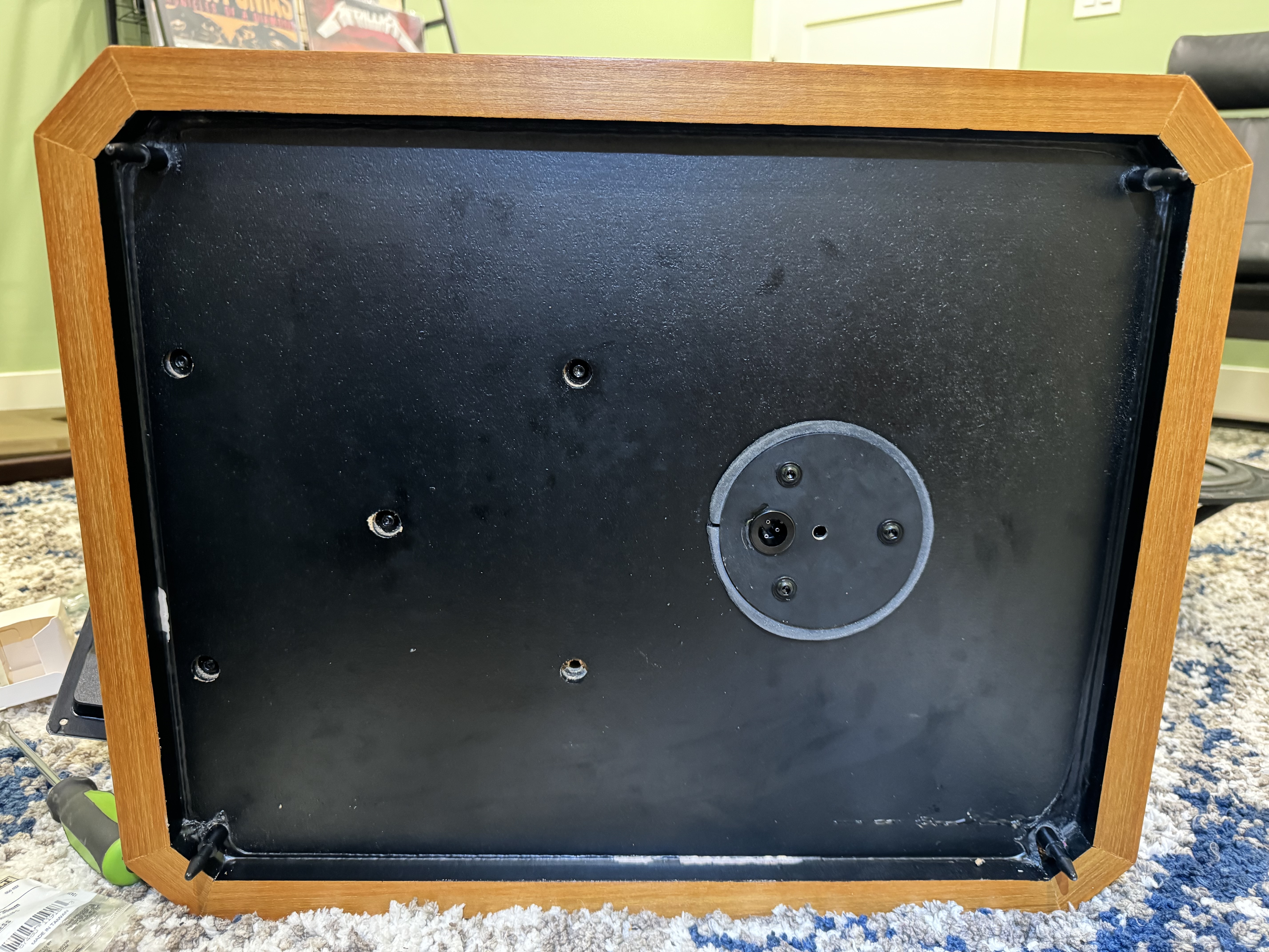
17) Shot of the inside with the woofer crossover removed
18) Shot of the top with the crossover removed
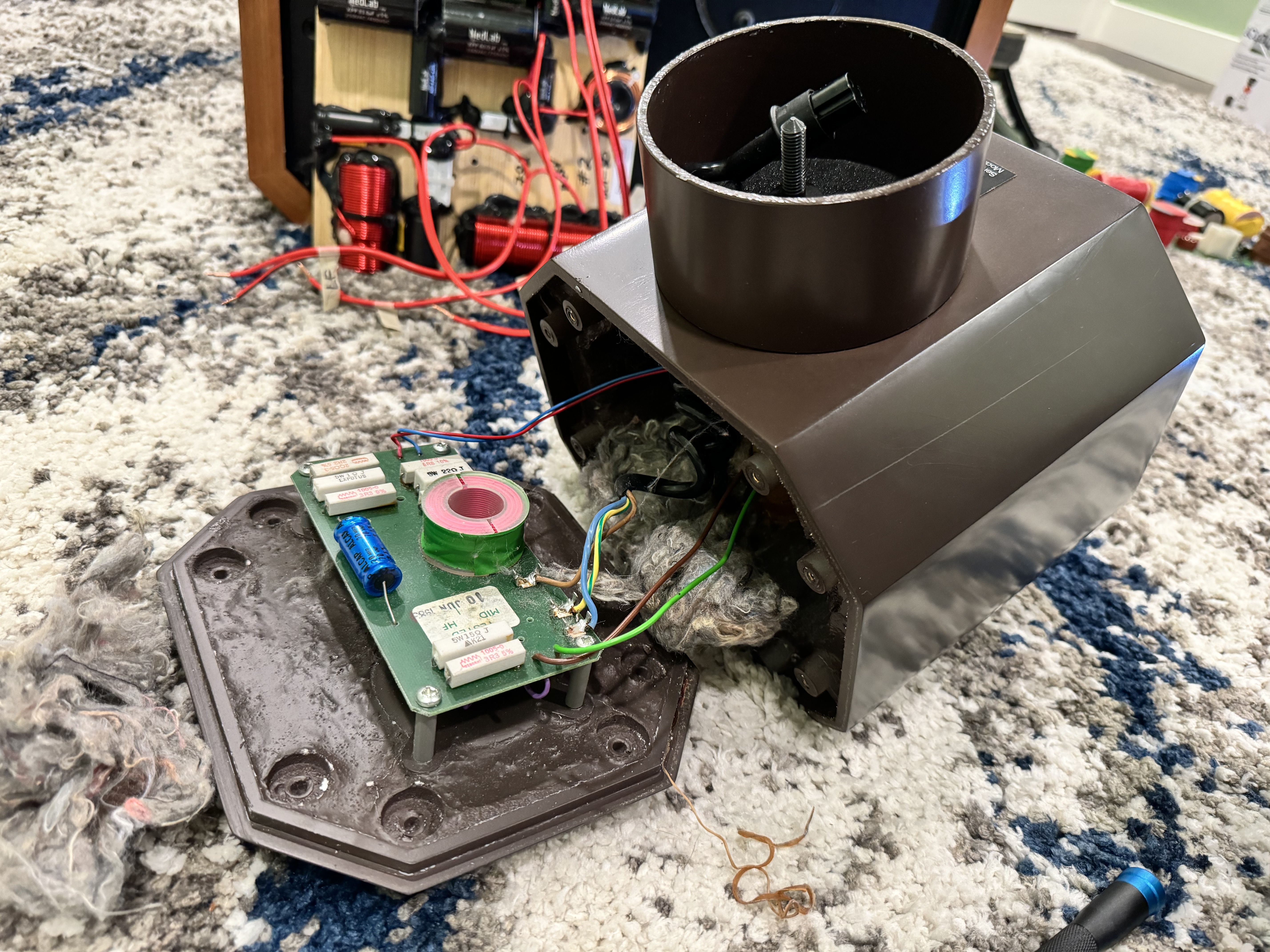
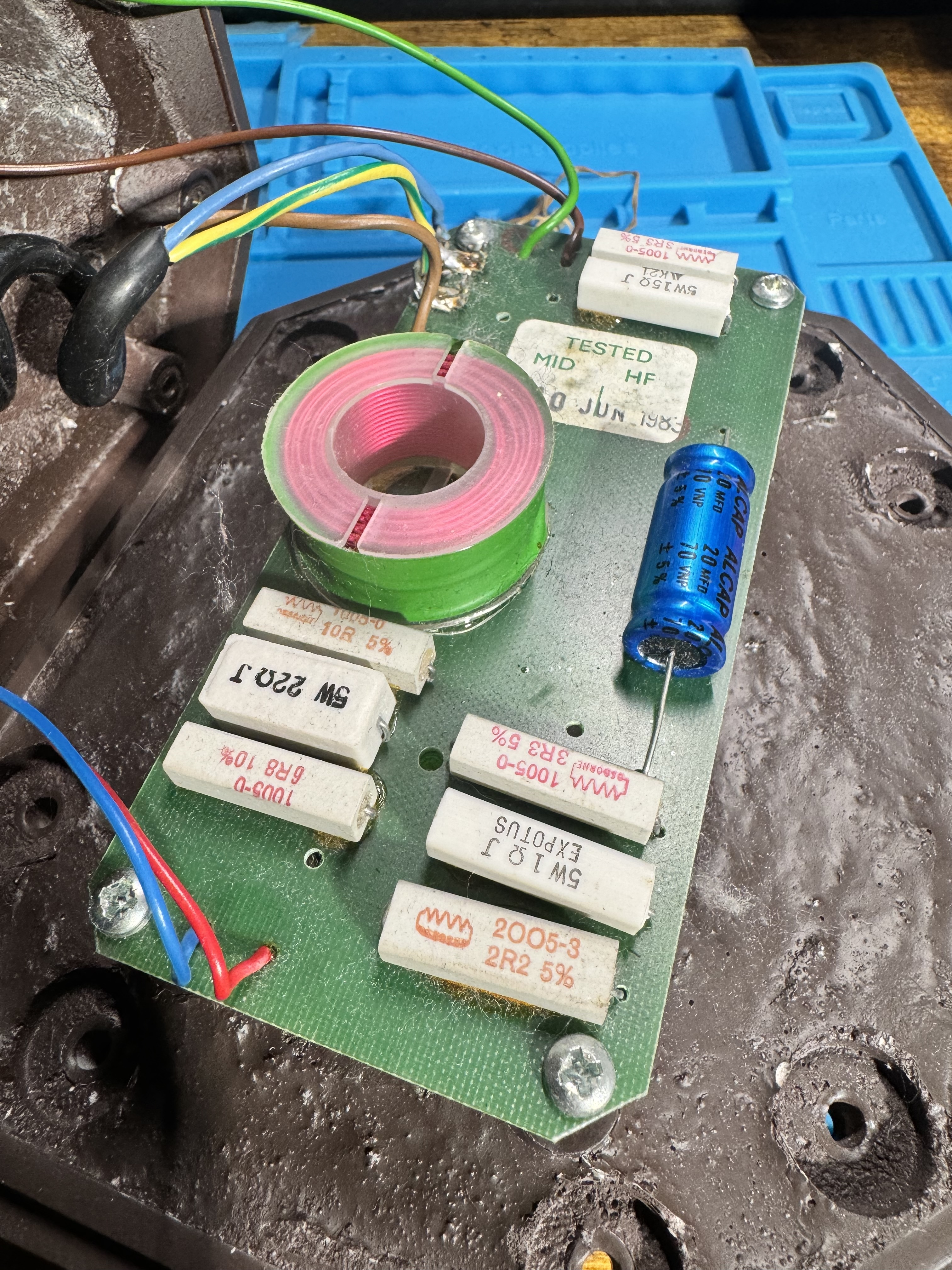
19) Let's take apart the mid-range + tweeter head! I had to remove the mid-range driver from the front to punch out the back once its screws were removed. Note the rubber band that helped it seal, this was also glued in
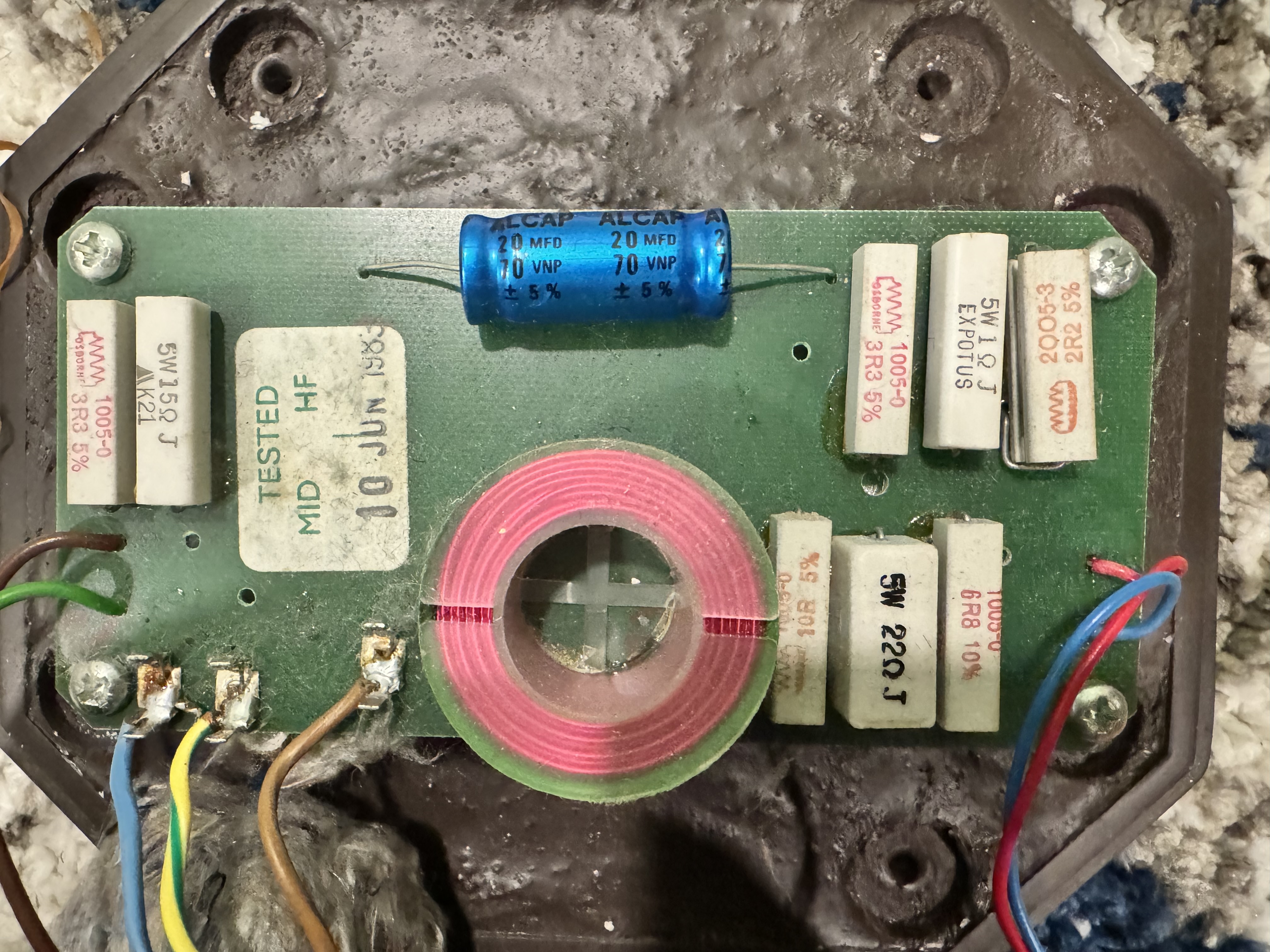
20) Another shot of the mid-range + tweeter crossover and environment controls board. June 10, 1983 for the this component
21) Yet another shot
22) Day #2, let's cut some wires!
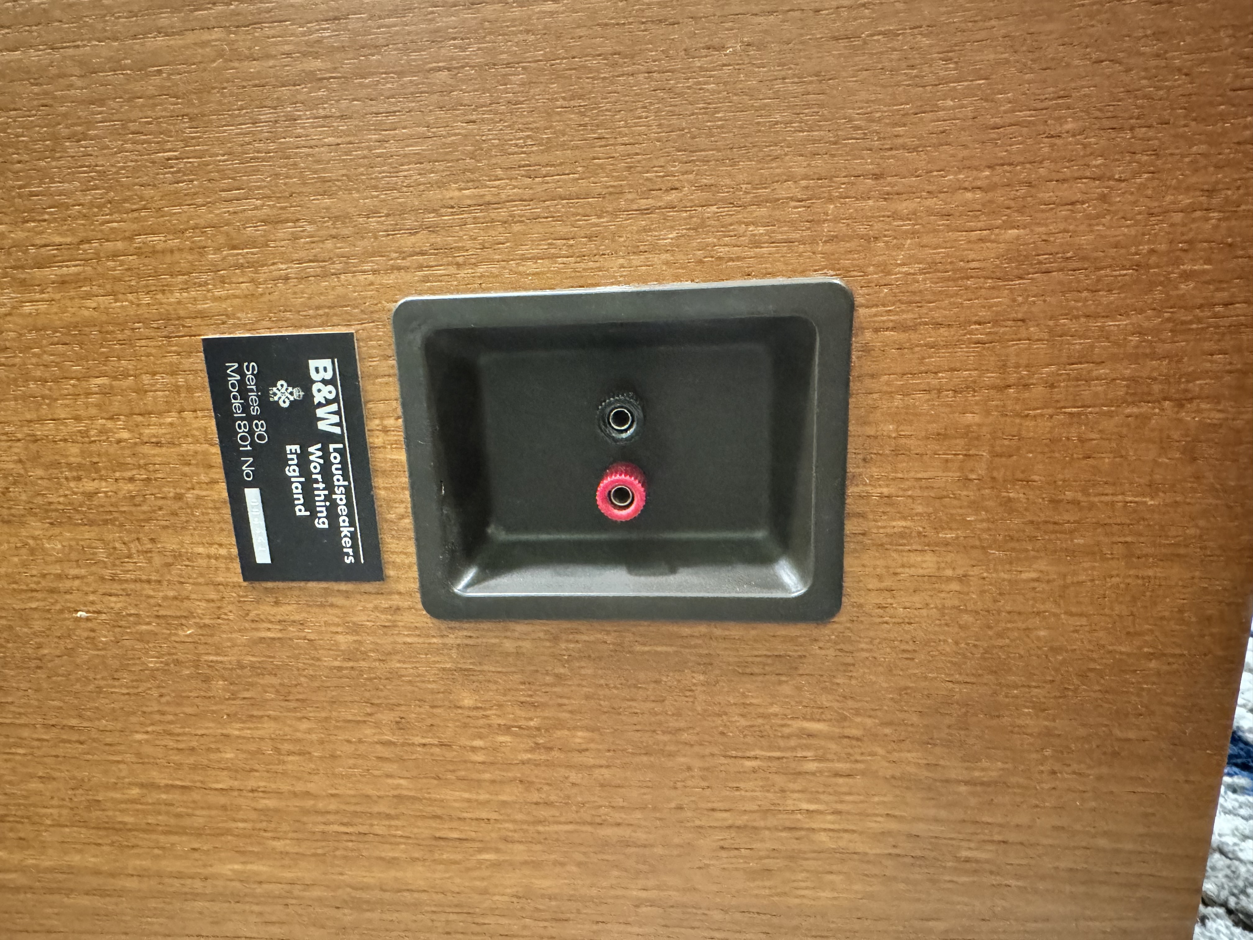
23) Removed the head mounting plate
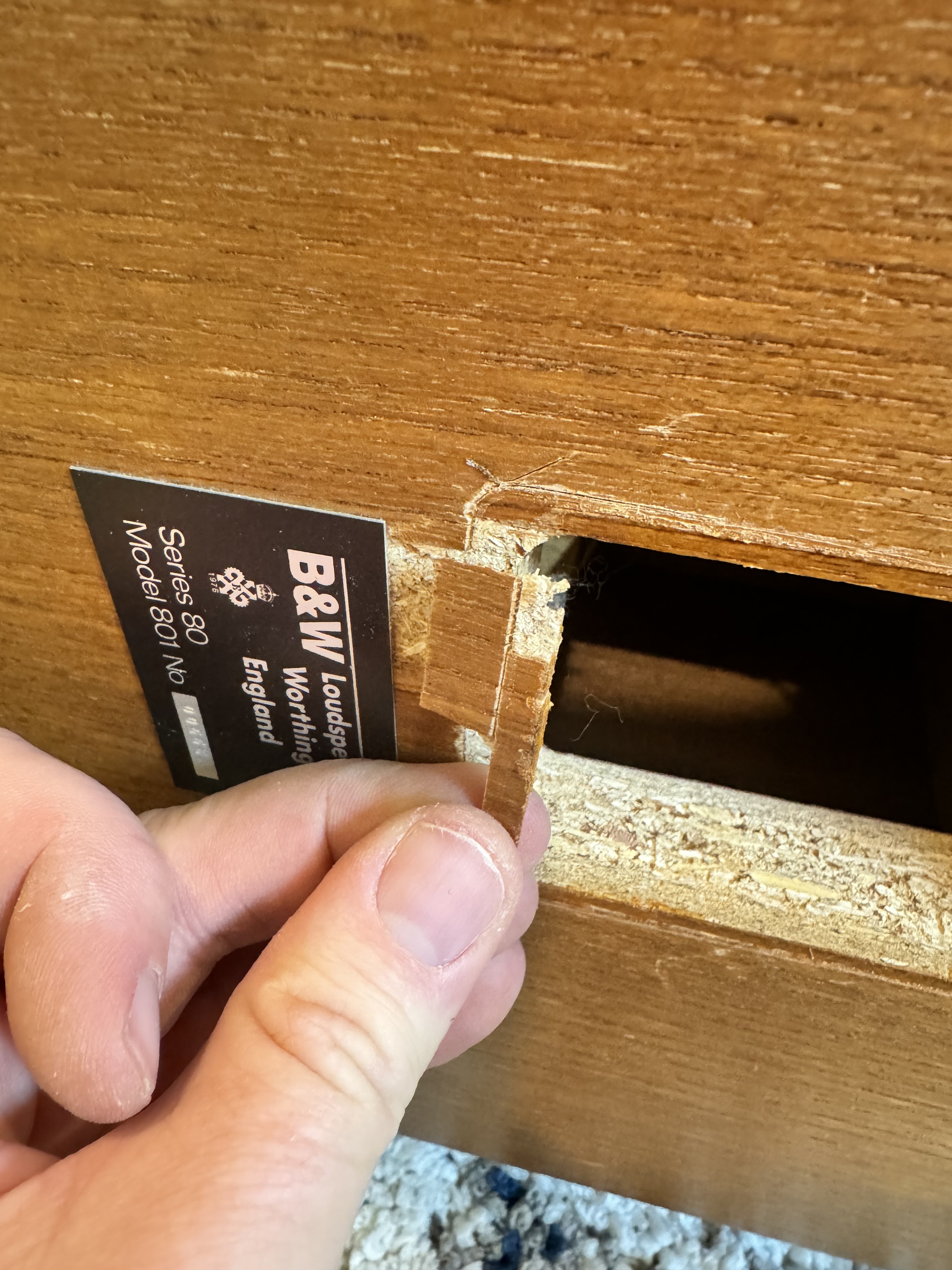
24) The original binding post cup is going to be removed. This is glued in unfortunately, so I scored the edges of the veneer and punched out the cup from the inside
25) Bummer, some of the veneer came off, you can see the evidence of my scoring around the edges of the binding post cup here
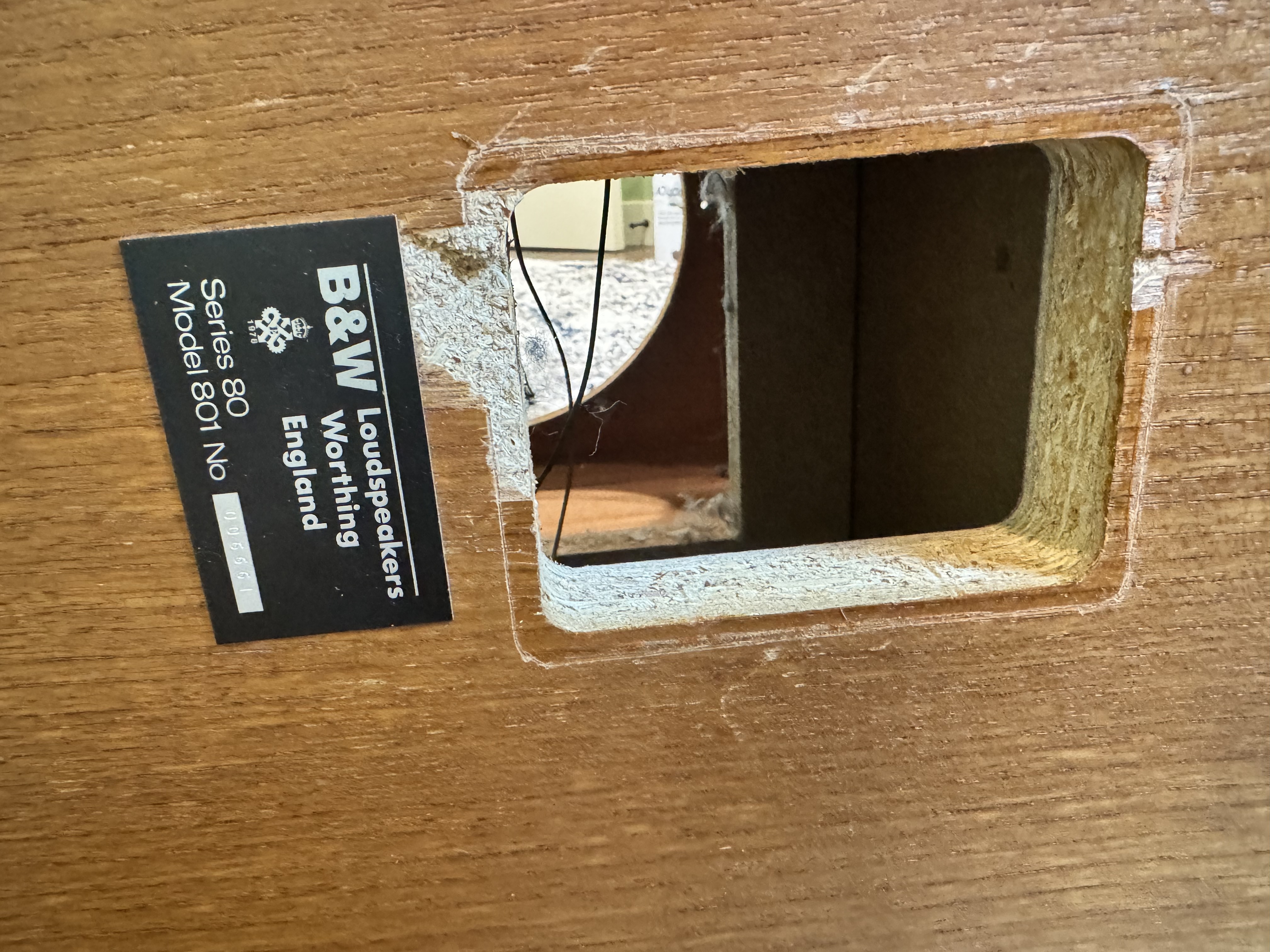
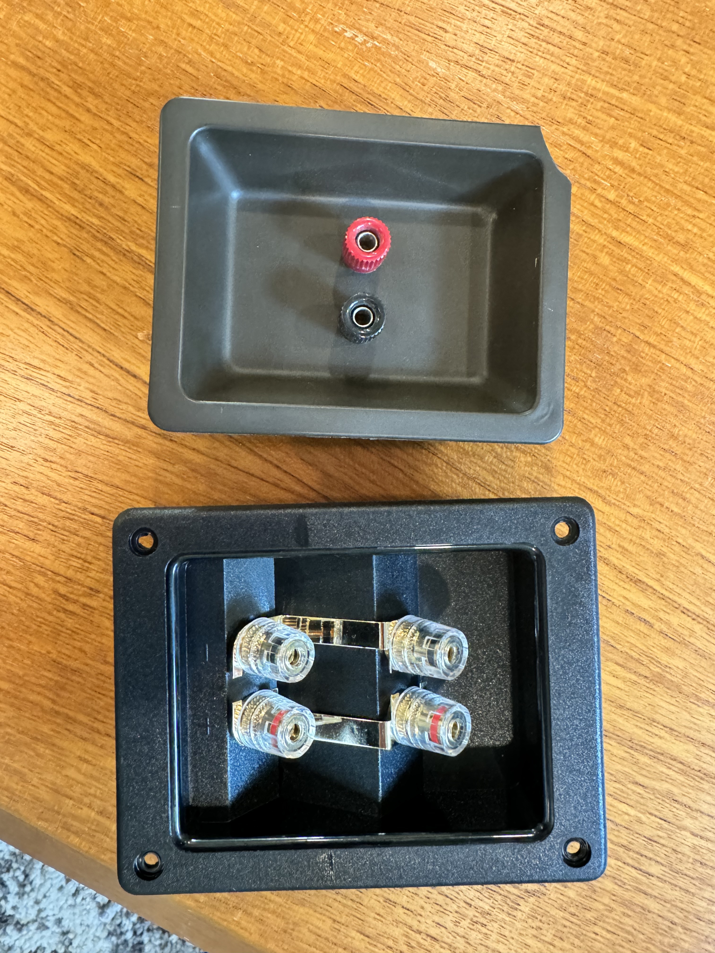
26) Original binding cup removed, time to take it outside!
27) Old binding cup vs new binding cup with HF and LF posts. The new cup is bigger so we have to modify the box to accomodate
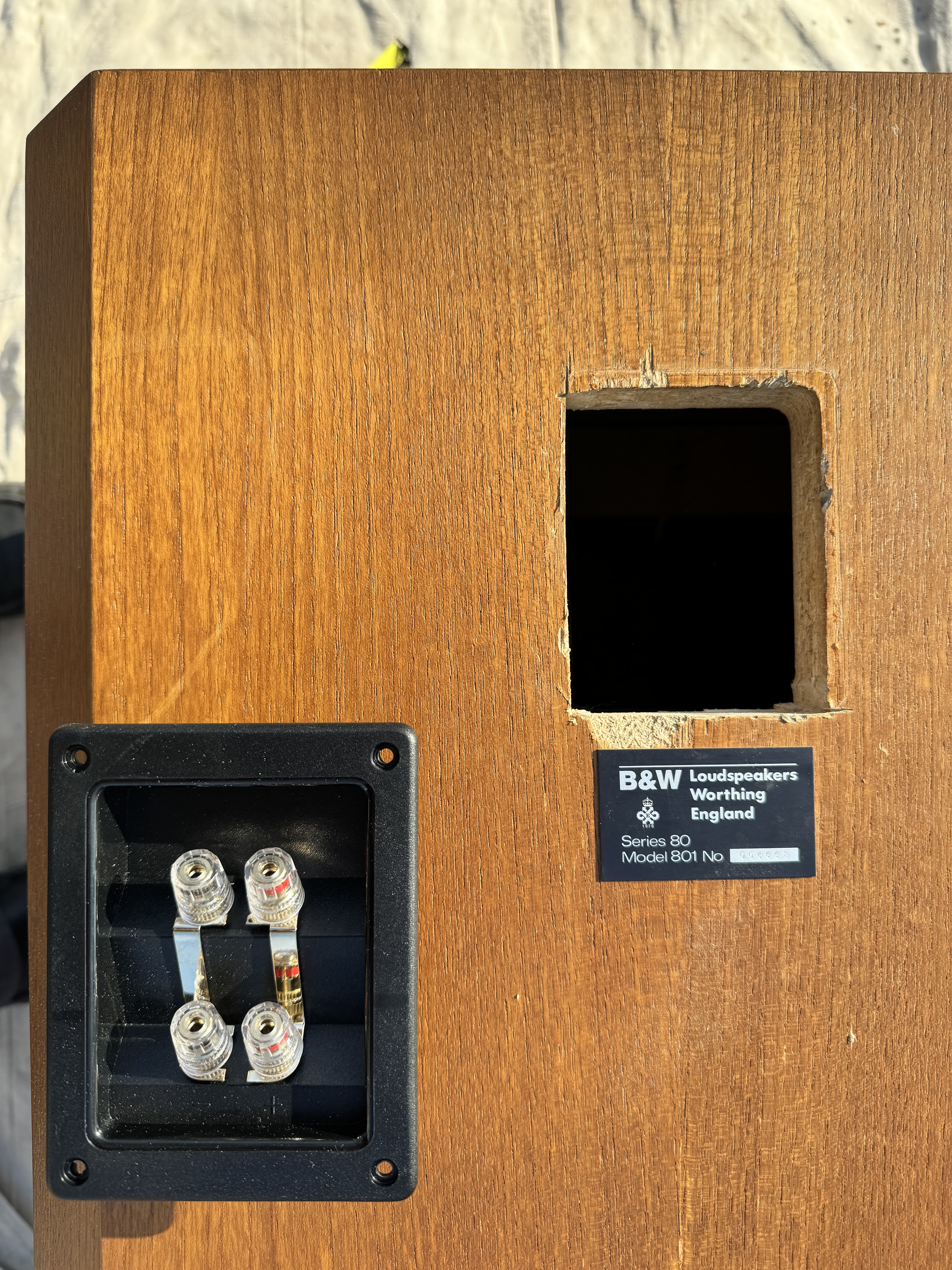
28) After some cutting of 2 sides
29) It fits! Slightly off center, but who will notice? This is the back of the speaker, after all. New cup covers the busted veneer, woot!
30) You can see where I cut (bottom) in this shot
31) It was a glorious winter day with the sun shining, had to take a pic to show how good of shape the veneer is in
32) So, the new crossover board doesn't line up with the same hole pattern as the original woofer crossover. Time to make an adapter board that can be screwed into the original holes on one side and the new crossover on the other
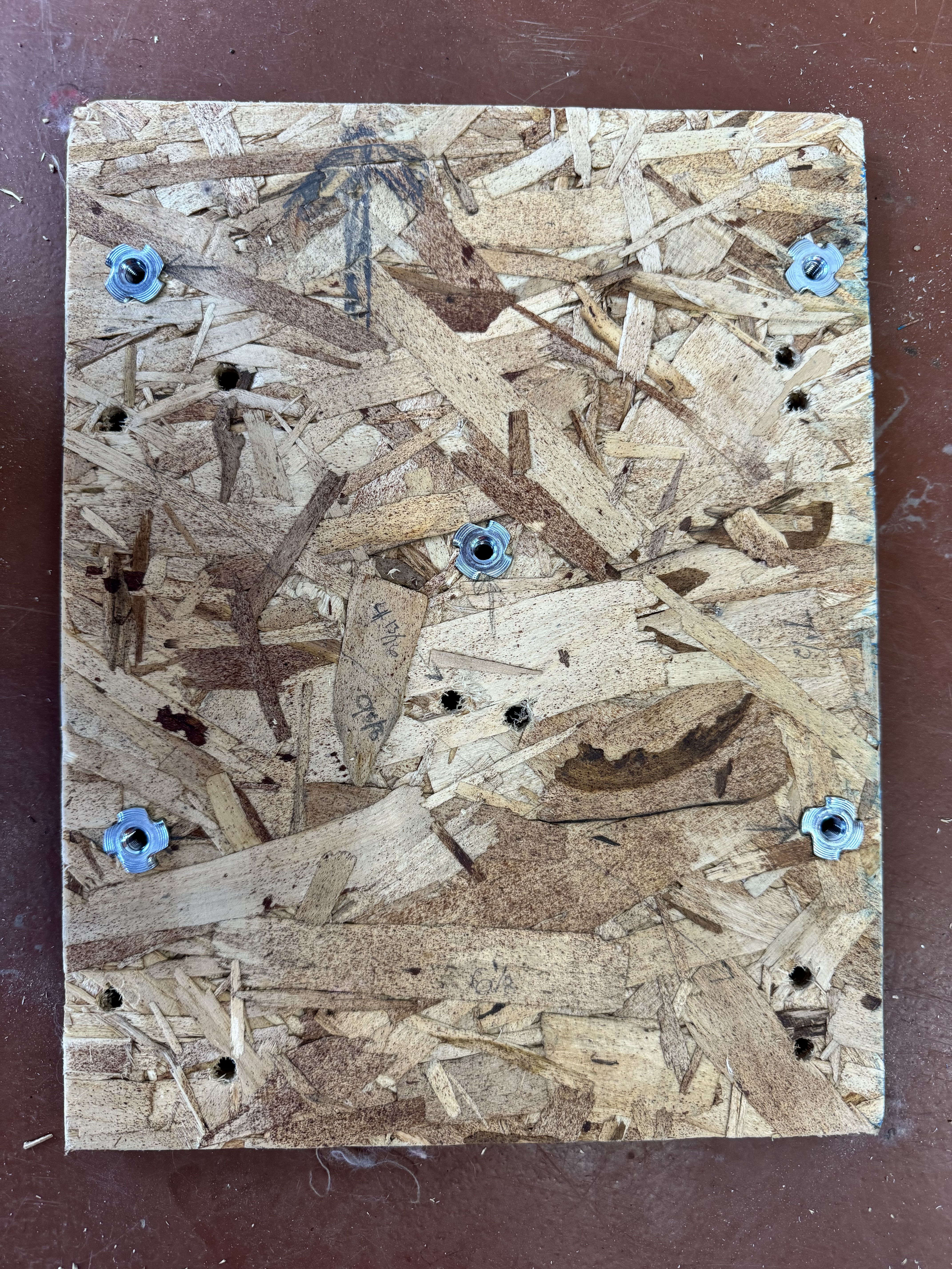
33) New crossover mounted to adapter board. I actually put 3 more screws in after taking this pic, because why not?
34) Bottom of the adapter board. I used tee nuts so the mounting screws would suck the board into the box
35) Shot of the tee nuts on the adapter board
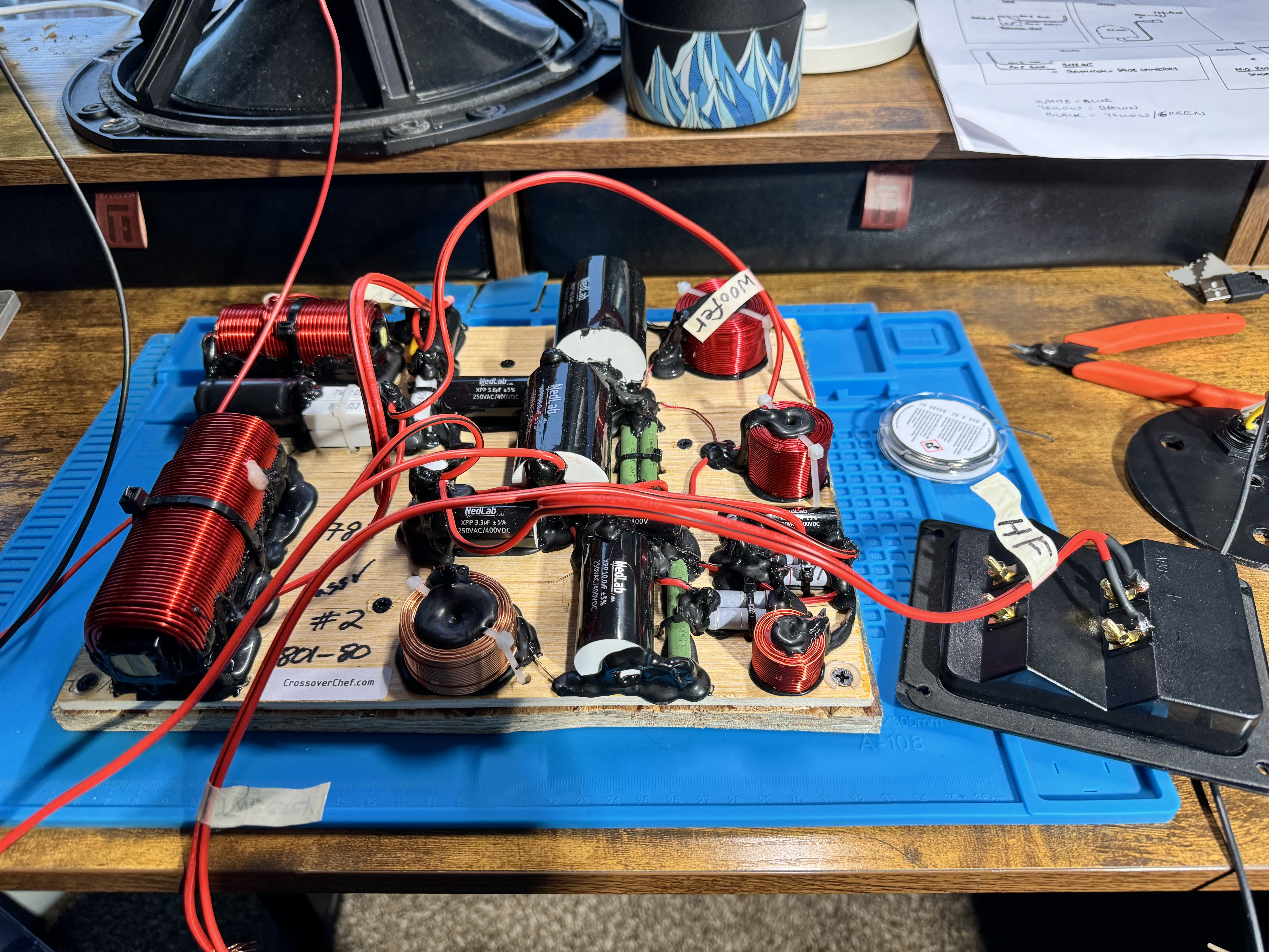
36) Soldering time! Attaching the High Frequency (HF) wires to the new binding posts
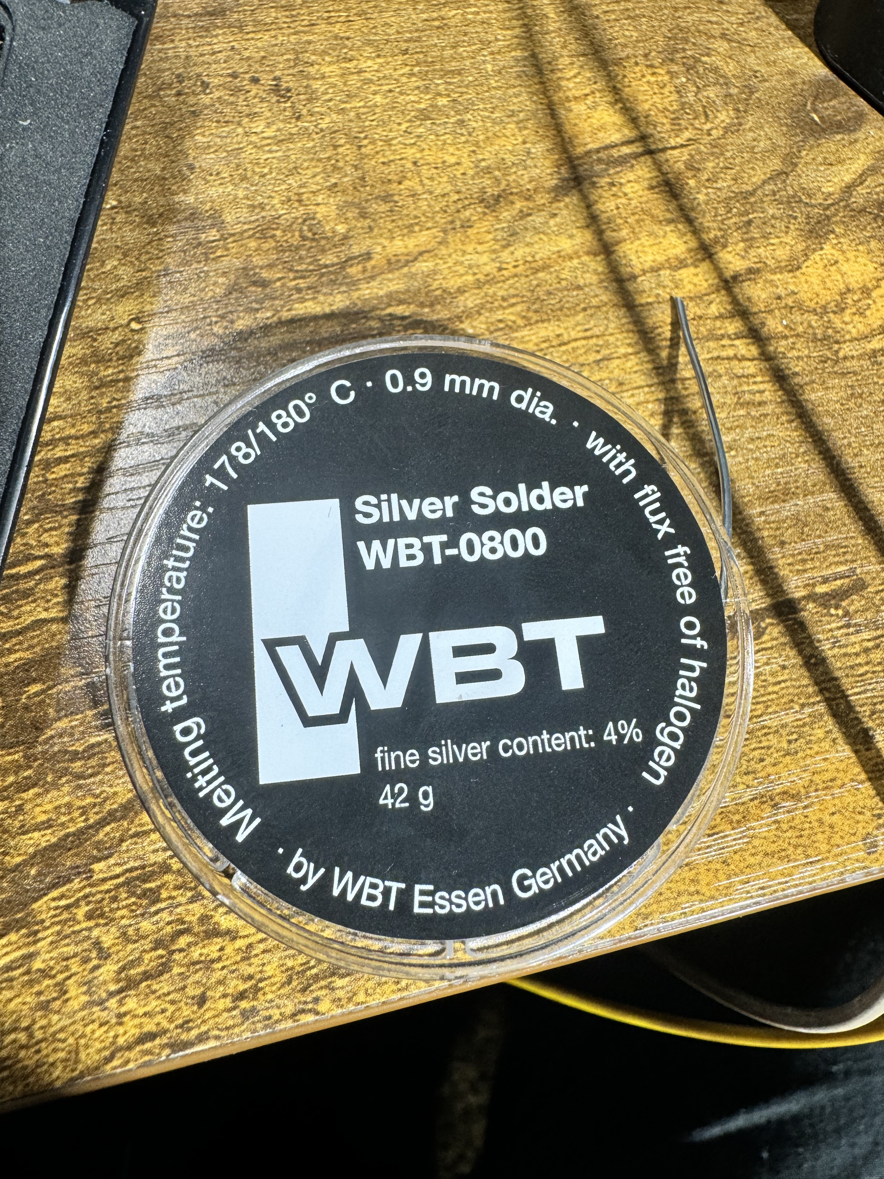
37) Shot of the work area
38) The solder I used - WBT-0800 . This stuff was actually excellent to work with
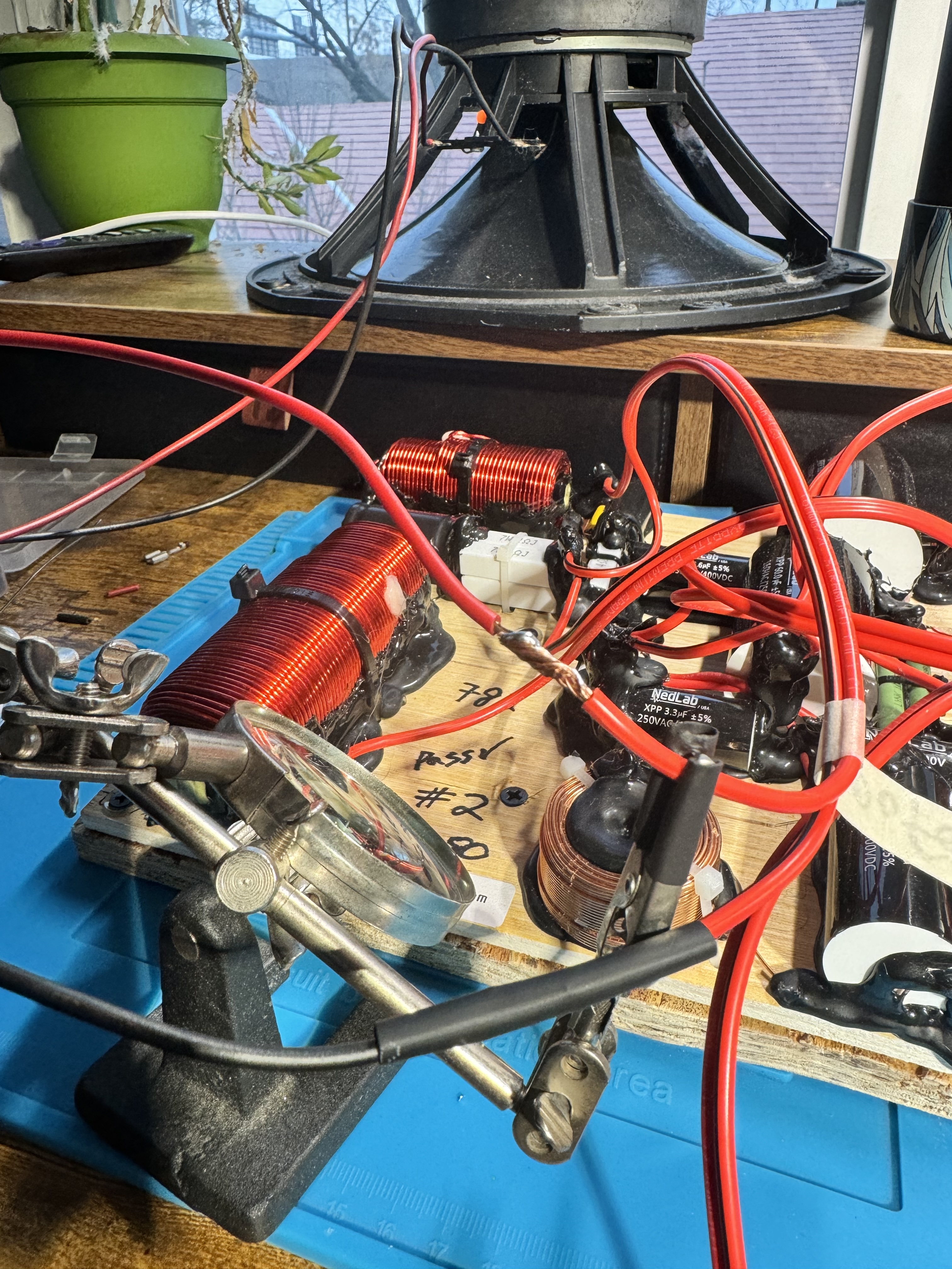
39) Attached the Low Frequency (LF) inputs
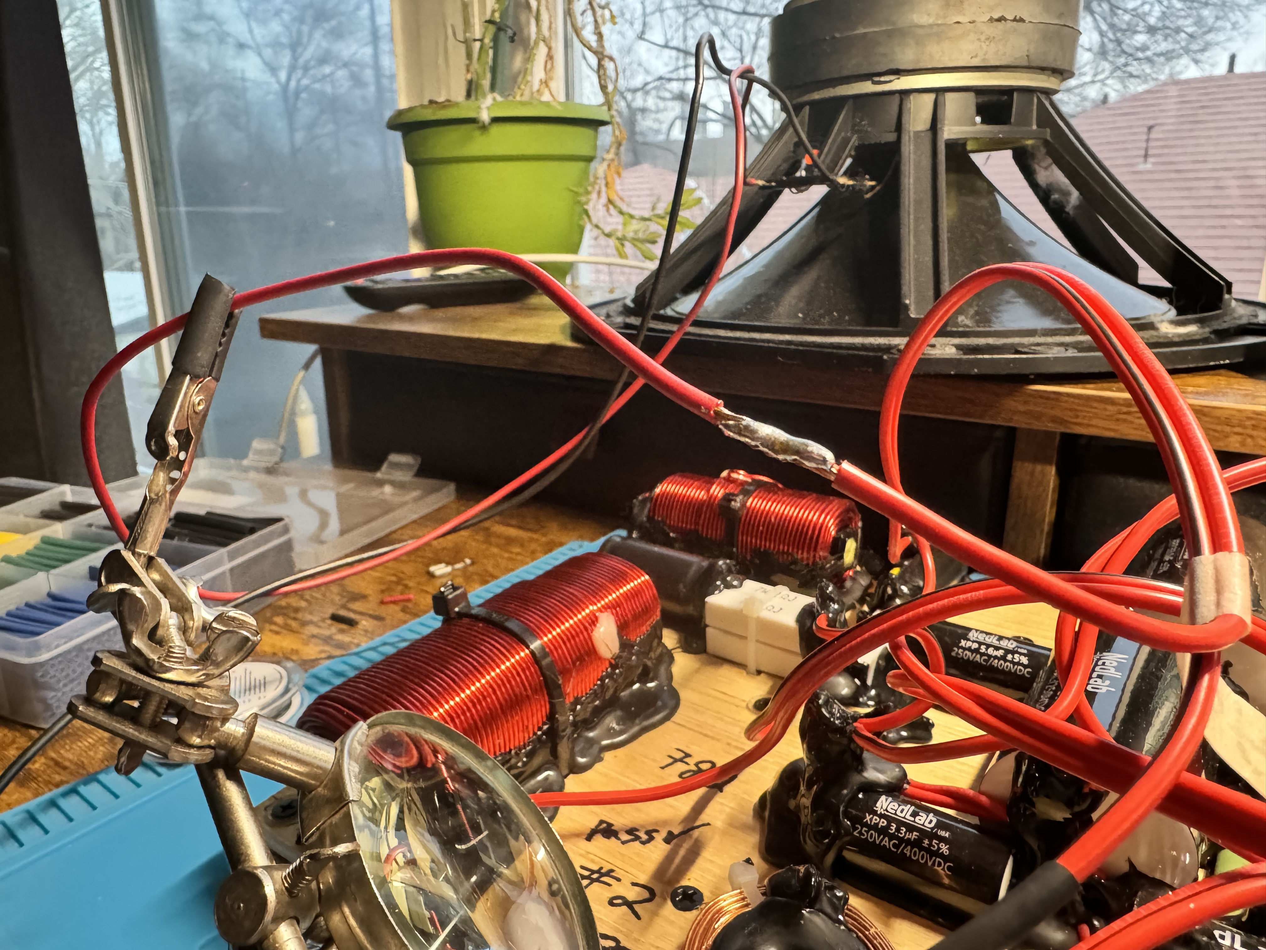
40) Soldering in the woofer
41) Another shot of the woofer solder process
42) More soldering. I kept forgetting to put heat shrinks on before joining the wires so some electrical tape was used. No one will ever see it, but whoops!
43) Here I'm joining the mid-range positive (+) to the correct output wire on the new crossover
44) And complete!
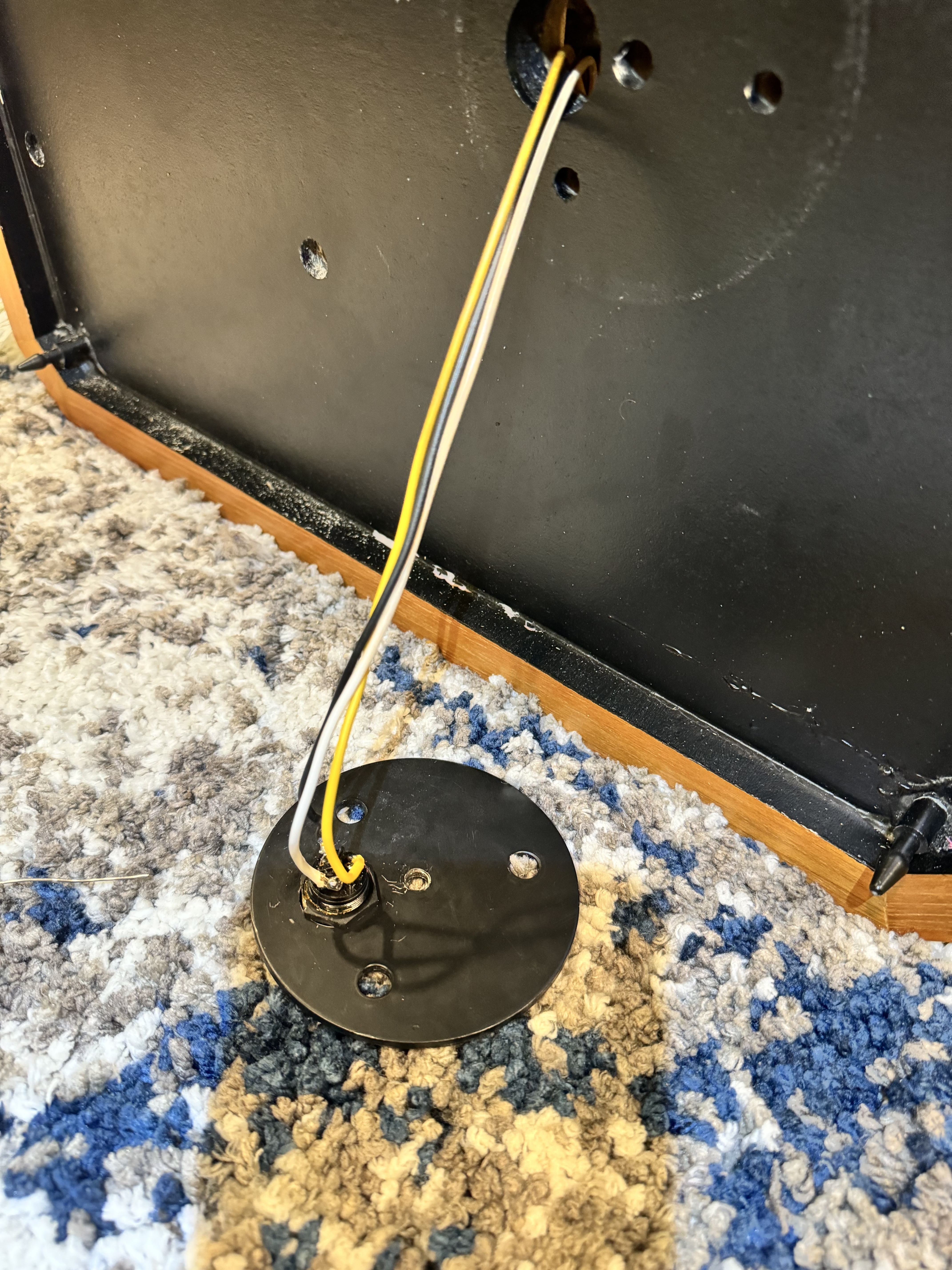
45) Another shot of everything complete. I joined the negative (-) leads of the mid-range + tweeter together. These go to the black wire on the 3-pin connector. The yellow is the mid-range positive (+) and the white is the tweeter positive (+).
46) Wiring diagram that came with the new crossovers (page #1), completely accurate and very helpful!
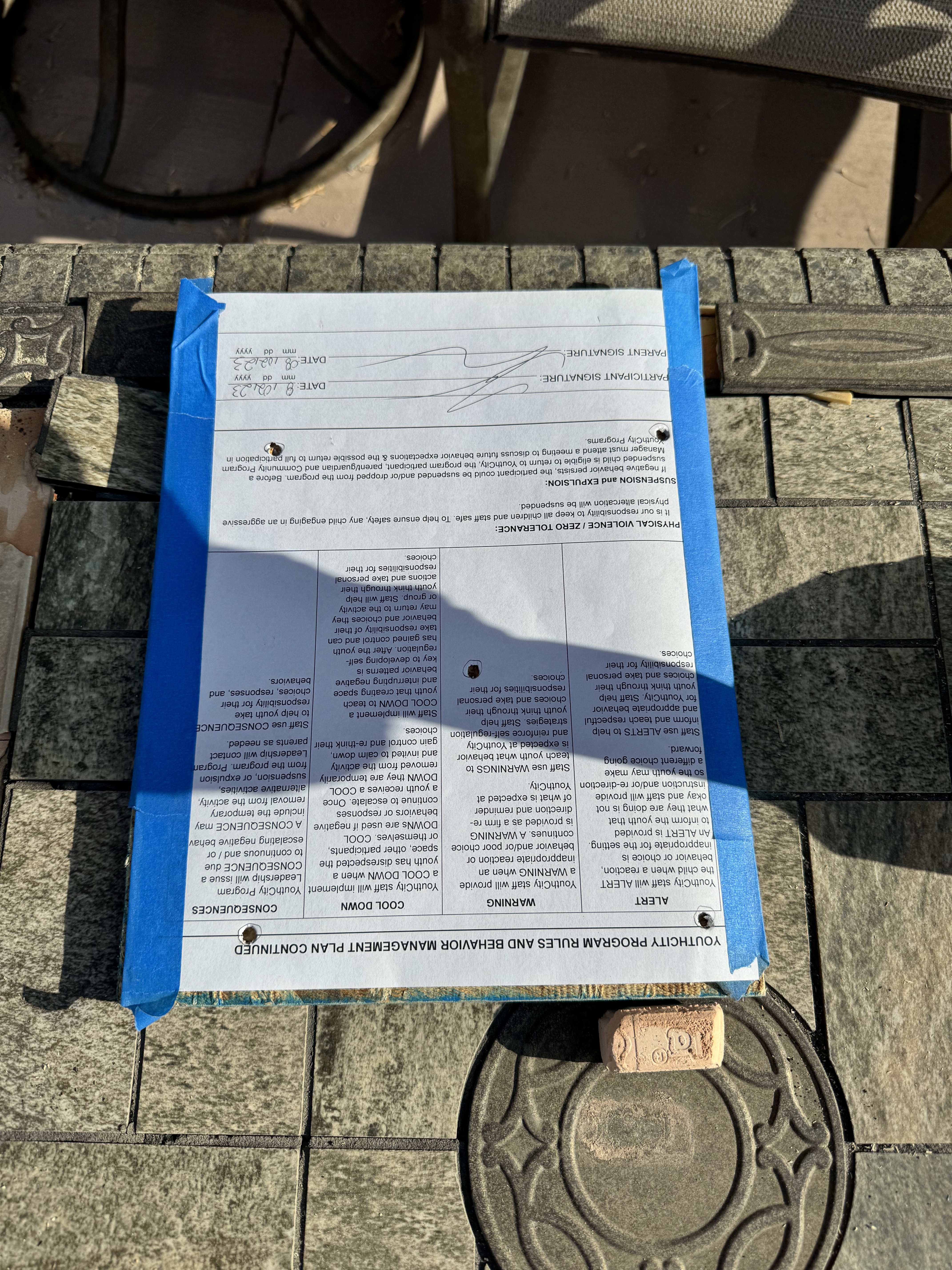
47) Page #2 of the wiring diagram that came with the new crossovers. The hand written notes at the bottom are how the 3-pin connector wires translate to the mid-range + tweeter pass through wires in the heads
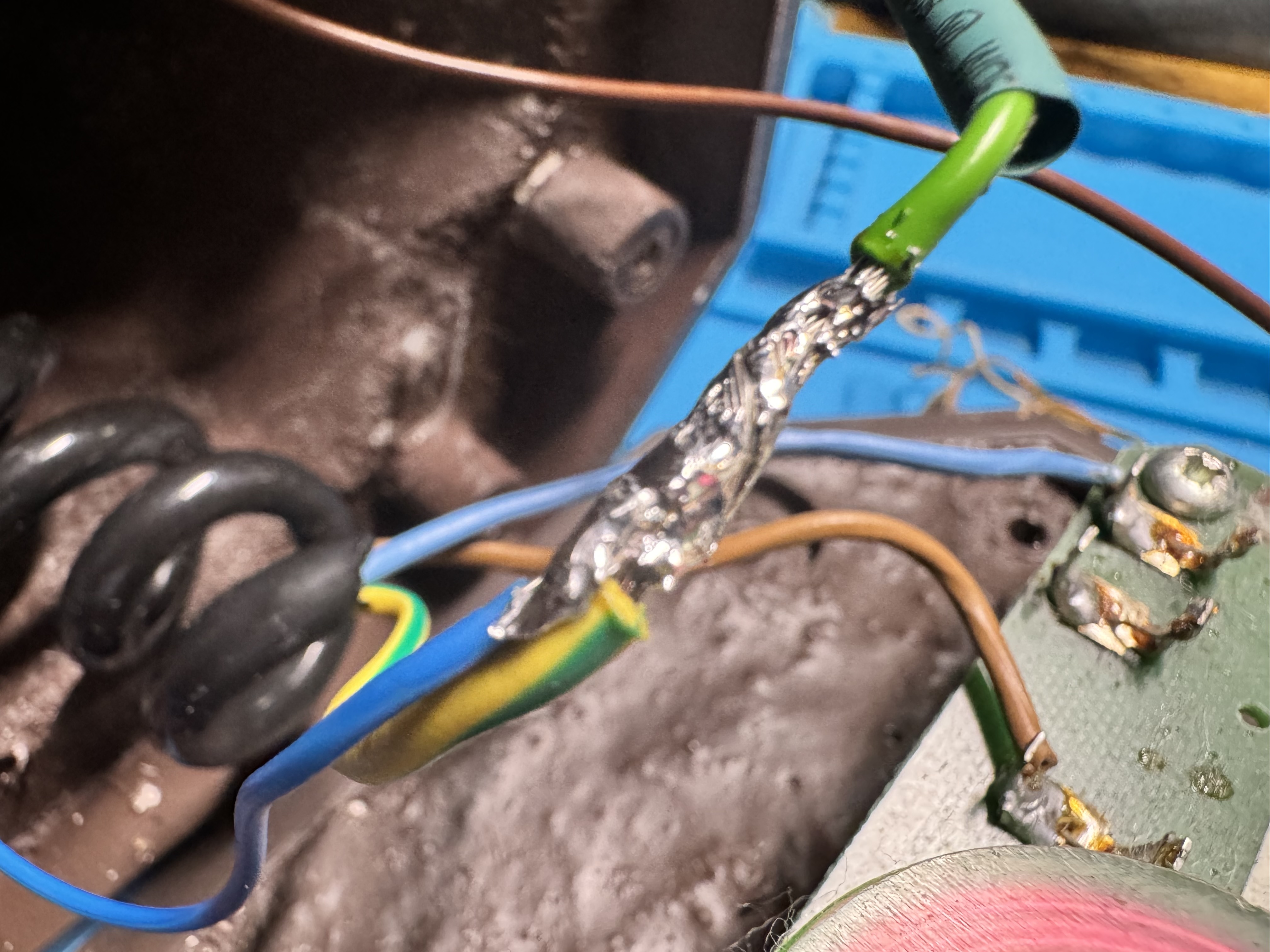
48) Time to bypass the crossover and environment controls and solder the mid-range + tweeter connectors
49) Super blurry shot of the shared ground connection (-) for the mid-range + tweeter
50) Connecting the mid-range positive (+)
51) Final testing before putting it all back together. Yup, everything works!
52) Stuffing the wool + wires back into the mid-range + tweeter head
53) Another shot of the head with the (now disconnected) crossover attached to the back ready to go on
54) New crossover mounted where the old one was
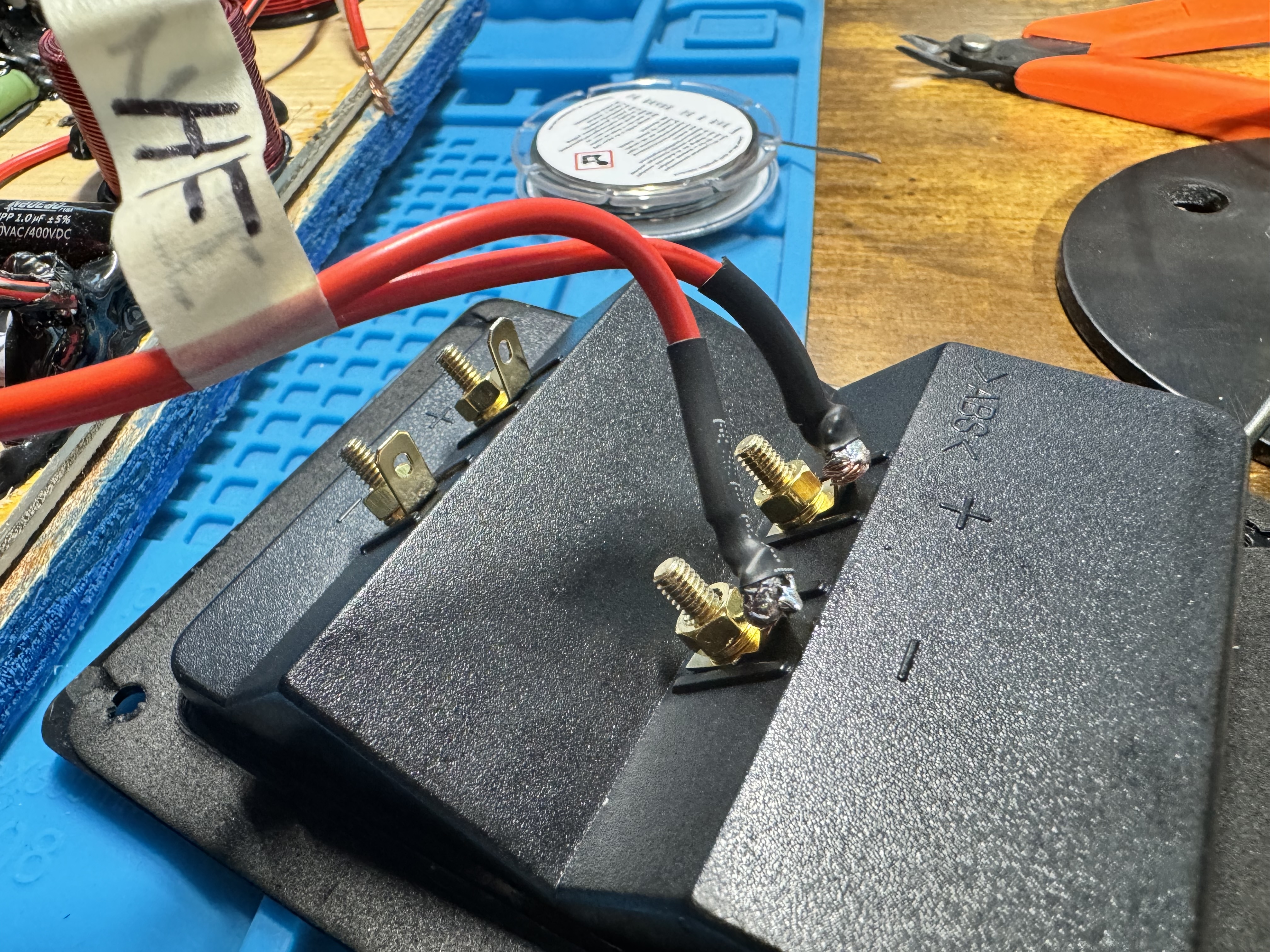
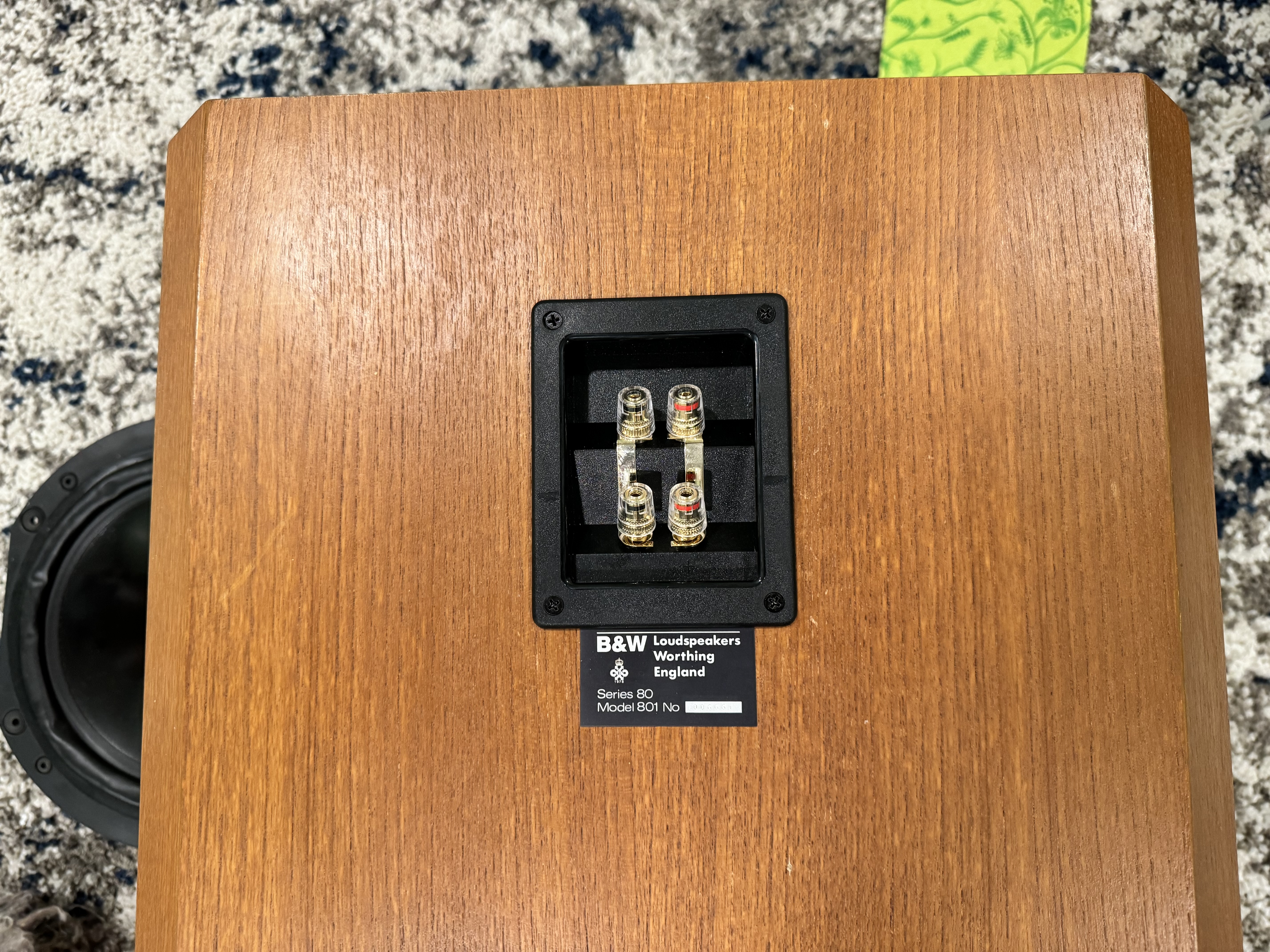
55) New binding post cup ready to be installed
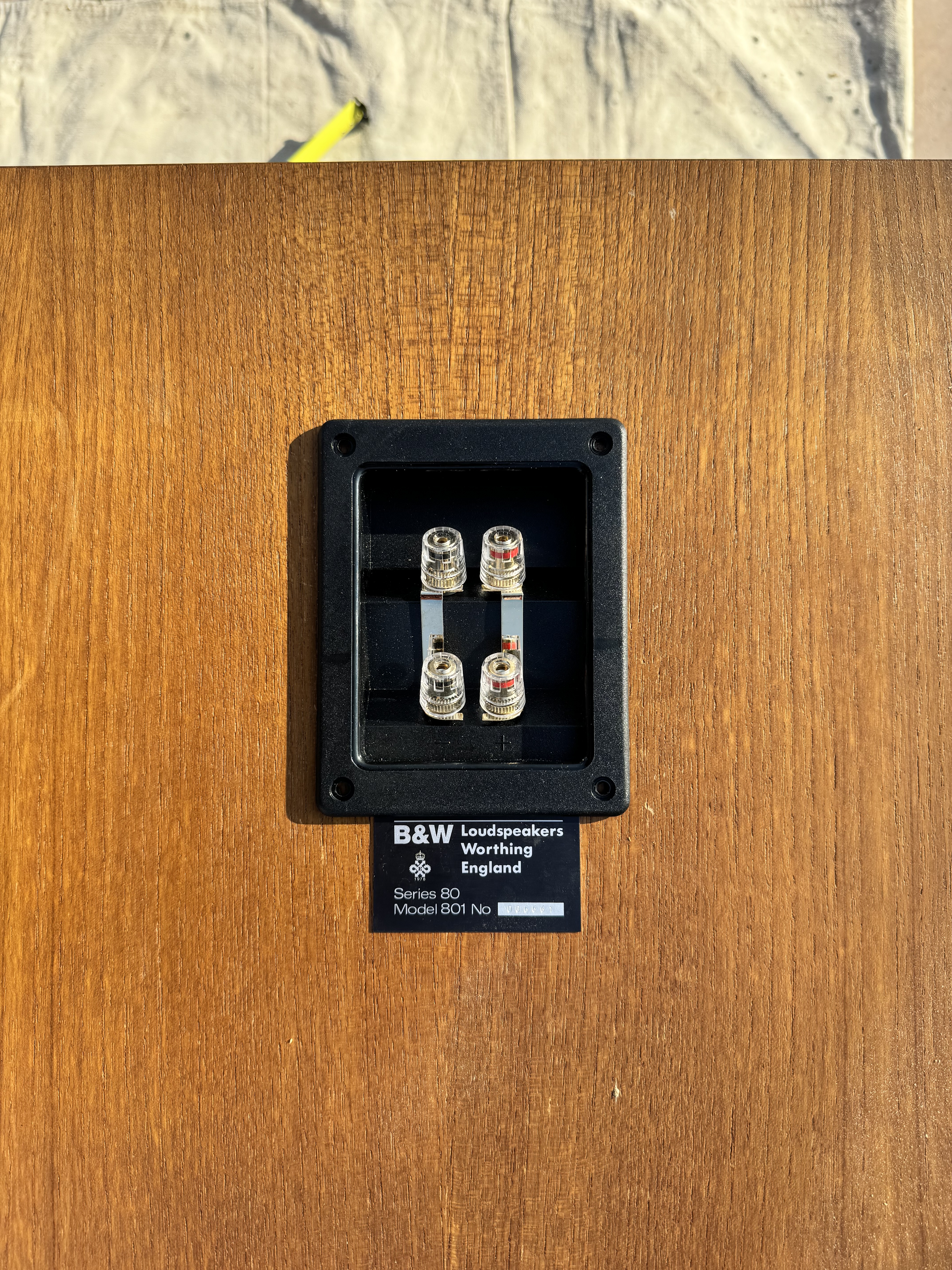
56) Binding post cup installed, it looks great!
57) Uh oh, I messed up soldering these wires to the crossover. Had to de-solder them so I could remove the mounting plate for the head and attach it properly
58) Ok, now we're connected in the correct order
59) Everything mounted up. I used new M6-1.0 x 30mm flanged button head socket cap hex screws to mount the crossover adapter board + the head mounting plate
60) Wool put back in, final step before re-attaching the woofer. The woofer was sitting upside down for awhile, which is why it looks slightly deformed here. It will be fine and return to it's original shape
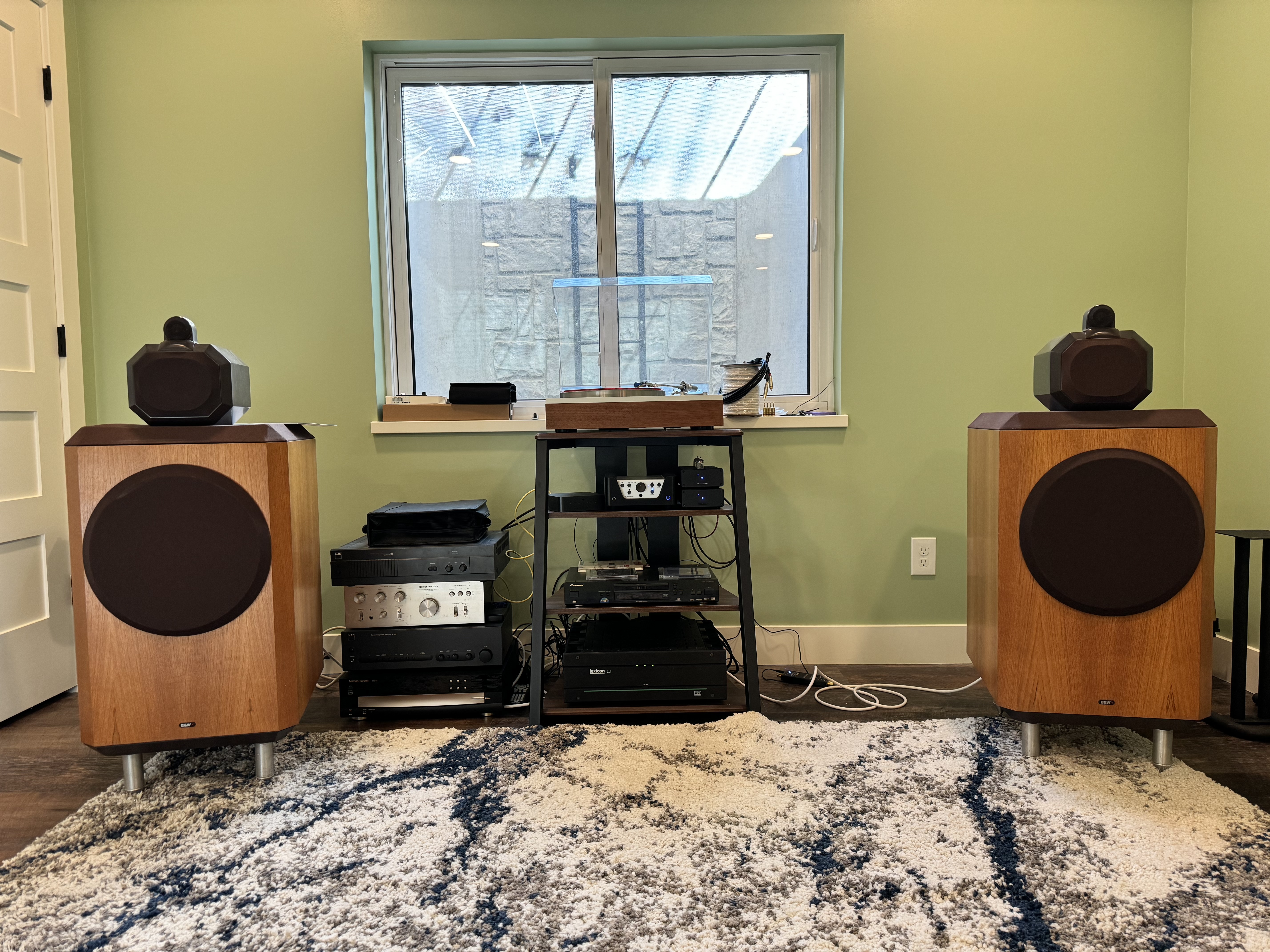
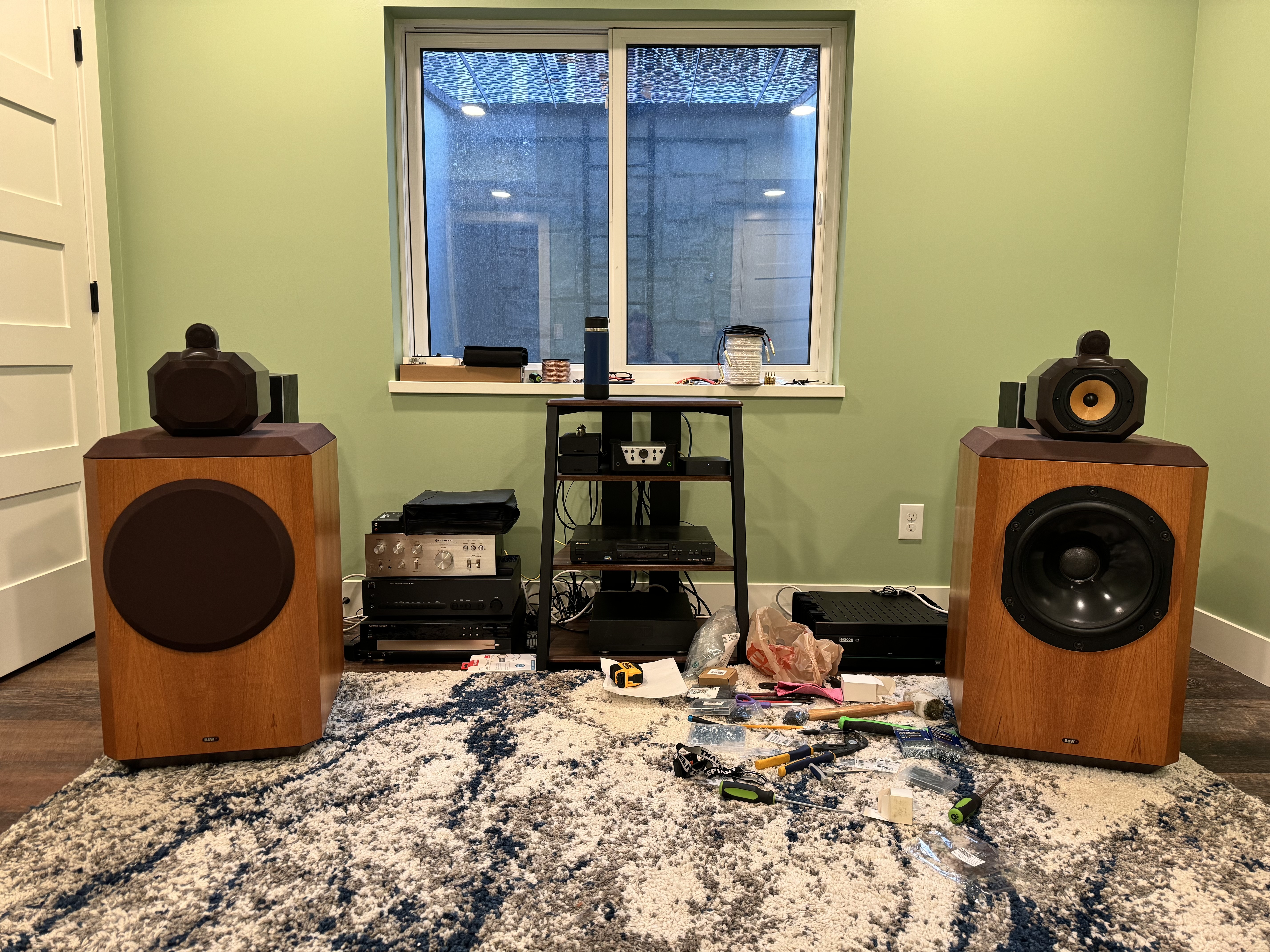
61) She's alive! Works great, time to hook up the second speaker to compare!
62) One on the right is the rebuilt one. At first blush the bass is certainly better. The mid and highs are different, not sure if I'd say better. I think the crossover needs some break in time too. Definitely sounds like a new speaker